1OPERATION_.pdf - 第90页
Page 2 - 42 2.13 Shut - Down Operation ( End of Production ) • - 2.14 Automatic Operation ( “ PASS ” Mode ) 2.14 . 1 Start Procedure of Automatic Operation ( “ PASS ” Mode ) 2.14 . 2 Stop Procedure of Automatic Operation…
Page
2
-
30
2.8
Setting
of
Operation
Mode
2.8
.
1
Automatic
Feeder
Axis
Adjustment
Mode
•
2.8
.
2
Overall
Tact
Time
Reduction
2.8
.
3
Shortage
of
Component
Detection
Mode
•
…
2.8
.
4
Alternate
Mode
2.8
.
5
Recovery
Mode
2.8
.
6
Feeder
Carriage
Axis
Mode
2.8
.
7
X
/
Y
Table
Axis
Mode
2.8
.
8
Trash
Box
Fill
Up
Warning
Mode
2.9
Starting
,
Emergency
Stop
and
Temporary
Stop
(
Pause
)
Operations
for
Automatic
Operation
(
“
PLACE
”
Mode
)
2.9
.
1
General
Start
2
-
30
2
-
30
2
-
30
2
-
30
2
-
30
2
-
30
2
-
30
2
-
30
2
-
31
2
-
31
and
Emergency
Stop
Procedures
2.9
.
2
Temporary
Stop
Procedure
of
Automatic
Operation
(
“
PLACE
”
Mode
)
2
-
33
2
-
33
2.9
.
3
Start
Procedure
from
“
PAUSE
”
Mode
2.9
.
4
Replacement
of
Tape
Feeders
during
Operation
2.10
Interruption
of
Automatic
Operation
(
“
PLACE
”
Mode
)
2.10
.
1
How
to
Interrupt
the
Automatic
Operation
2.10
.
2
Function
of
[
SYS
CLR
]
Button
2.11
Reset
and
Start
Procedure
from
Emergency
Stop
(
Automatic
Operation
(
“
PLACE
”
Mode
))
2.11
.
1
Cause
and
Symptom
of
Emergency
Stop
2.11
.
2
Reset
and
Start
Procedure
from
Emergency
Stop
(
Automatic
Operation
(
“
PLACE
”
Mode
}
)
…
.
2.12
Stopping
Automatic
Operation
(
“
PLACE
”
Mode
)
2.12
.
1
General
Stop
Procedure
2.12
.
2
Automatic
Stop
Procedure
2.12
.
3
Emergency
Stop
Procedure
2
-
34
2
-
36
2
-
36
2
-
36
2
-
38
2
-
38
2
-
38
2
-
41
2
-
41
2
-
41
2
-
41
9803
-
001
ACP
01
EOPCC
2
Page
2
-
42
2.13
Shut
-
Down
Operation
(
End
of
Production
)
•
-
2.14
Automatic
Operation
(
“
PASS
”
Mode
)
2.14
.
1
Start
Procedure
of
Automatic
Operation
(
“
PASS
”
Mode
)
2.14
.
2
Stop
Procedure
of
Automatic
Operation
(
“
PASS
”
Mode
)
2.15
Operation
Mode
of
Feeder
Carriages
2.16
Input
and
Selection
of
Program
Data
2.16
.
1
Input
of
Program
Data
2.16
.
2
Selection
of
Pattern
Program
Data
2
-
42
2
-
42
2
-
43
2
-
44
2
-
46
2
-
46
2
-
46
9803
-
001
ACP
01
EOPCC
2
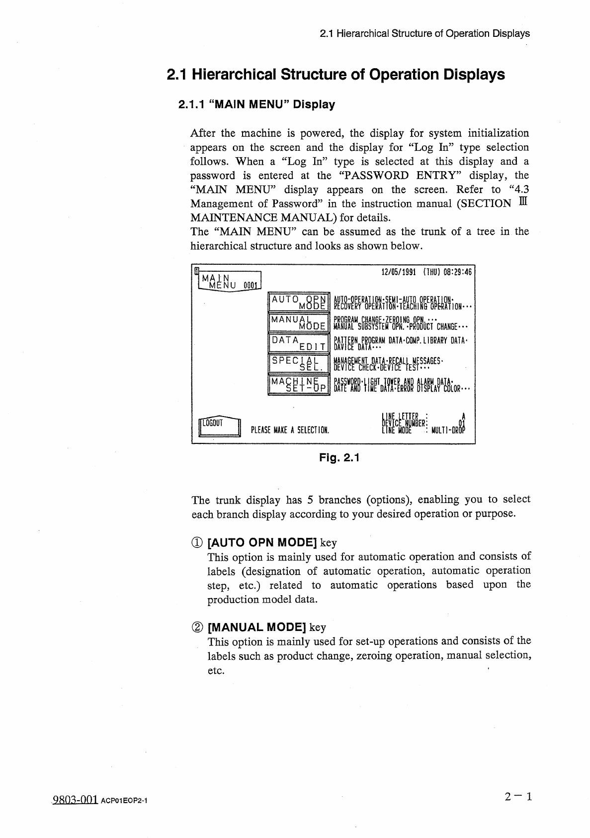
2.1
Hierarchical
Structure
of
Operation
Displays
2.1
Hierarchical
Structure
of
Operation
Displays
2.1
.
1
“
MAIN
MENU
”
Display
After
the
machine
is
powered
,
the
display
for
system
initialization
appears
on
the
follows
.
When
a
“
Log
In
”
type
is
selected
at
this
display
and
a
password
is
entered
at
the
“
PASSWORD
ENTRY
”
display
,
the
“
MAIN
MENU
”
display
appears
on
the
Management
of
Password
”
in
the
instruction
manual
(
SECTION
MAINTENANCE
MANUAL
)
for
details
.
The
“
MAIN
MENU
”
can
be
assumed
as
the
trunk
of
a
tree
in
the
hierarchical
structure
and
looks
as
shown
below
.
and
the
display
for
“
Log
In
”
type
selection
screen
Refer
to
“
4.3
screen
.
E
in
-
12
/
05
/
1991
(
THU
)
08
:
29
:
46
N
NU
0001
AUTOM
腳
HAIALMISYSIEM
^
N
.
^
PRODOCT
CHANGE
" "
"
PAT
|
|
NDP
^
GRAM
DATA
-
COMP
.
LIBRARY
DATA
-
■
疆擺
L
}
ES
,
ges
-
MANUA
8
DE
M
DATA
EDIT
瓶掛
.
iivKIF
%
um
-
Di
|
L
06
QUI
I
PLEASE
MAKE
A
SELECTION
.
Fig
.
2.1
The
trunk
display
has
5
branches
(
options
)
,
enabling
you
to
select
each
branch
display
according
to
your
desired
operation
or
purpose
.
①
[
AUTO
OPN
MODE
]
key
This
option
is
mainly
used
for
automatic
operation
and
consists
of
labels
(
designation
of
automatic
operation
,
automatic
operation
step
,
etc
.
)
related
to
automatic
operations
based
upon
production
model
data
.
the
②
[
MANUAL
MODE
]
key
This
option
is
mainly
used
for
set
-
up
operations
and
consists
of
the
labels
such
as
product
change
,
zeroing
operation
,
manual
selection
,
etc
.
2
一
1
ACP
01
EOP
2
-
1