1OPERATION_.pdf - 第155页
3.9 Device Information 3.9 Device Information • This display shows various information during automatic operation . After each information , automatic operation still continues . • Warning messages indicate that the mach…
3.8
One
-
Touch
Jump
Function
•
When
the
above
display
is
opened
,
pressing
the
[
START
]
button
validates
the
function
and
the
machine
can
easily
be
re
-
started
after
it
has
stopped
in
an
error
condition
.
Pressing
the
[
RTN
]
key
also
shifts
to
the
original
display
.
Therefore
,
the
operation
(
such
as
data
editing
)
or
display
(
such
as
management
data
information
)
being
performed
before
error
condition
can
be
easily
and
quickly
resumed
and
the
job
engaged
continuously
.
Notes
:
(
a
)
The
same
label
and
keys
as
the
“
AUTO
OPN
.
MODE
〈
PLACEMENT
〉
’
’
display
appear
on
this
display
except
the
“
〈
FEEDER
CHANGE
-
OVER
PREPARATION
COMPLETE
〉
”
keys
(
Cl
and
C
2
)
.
These
keys
appear
in
place
of
the
label
“
MGT
.
INFO
.
”
and
its
data
field
.
The
“
AUTO
OPN
.
SUB
-
MENU
”
display
cannot
be
opened
from
this
display
.
(
b
)
The
[
FEEDER
RETURN
]
button
on
the
rear
touch
screen
can
be
used
.
The
[
FEEDER
RETURN
]
button
screen
is
not
ready
for
use
.
the
front
touch
on
3
-
17
01
07
-
002
ACP
01
EOP
3
-
17
3.9
Device
Information
3.9
Device
Information
•
This
display
shows
various
information
during
automatic
operation
.
After
each
information
,
automatic
operation
still
continues
.
•
Warning
messages
indicate
that
the
machine
is
under
low
operation
rate
(
nozzle
and
feeder
message
rate
)
based
upon
the
set
operation
parameters
,
the
nozzle
which
causes
poor
handling
rate
is
automatically
bypassed
for
a
smooth
operation
(
function
to
prohibit
the
use
of
the
nozzle
automatically
)
,
the
machine
is
almost
short
of
components
,
etc
.
•
The
conditions
to
issue
device
information
according
to
the
operation
parameters
set
in
data
editing
.
(
Operation
parameters
can
be
set
not
to
issue
device
information
.
)
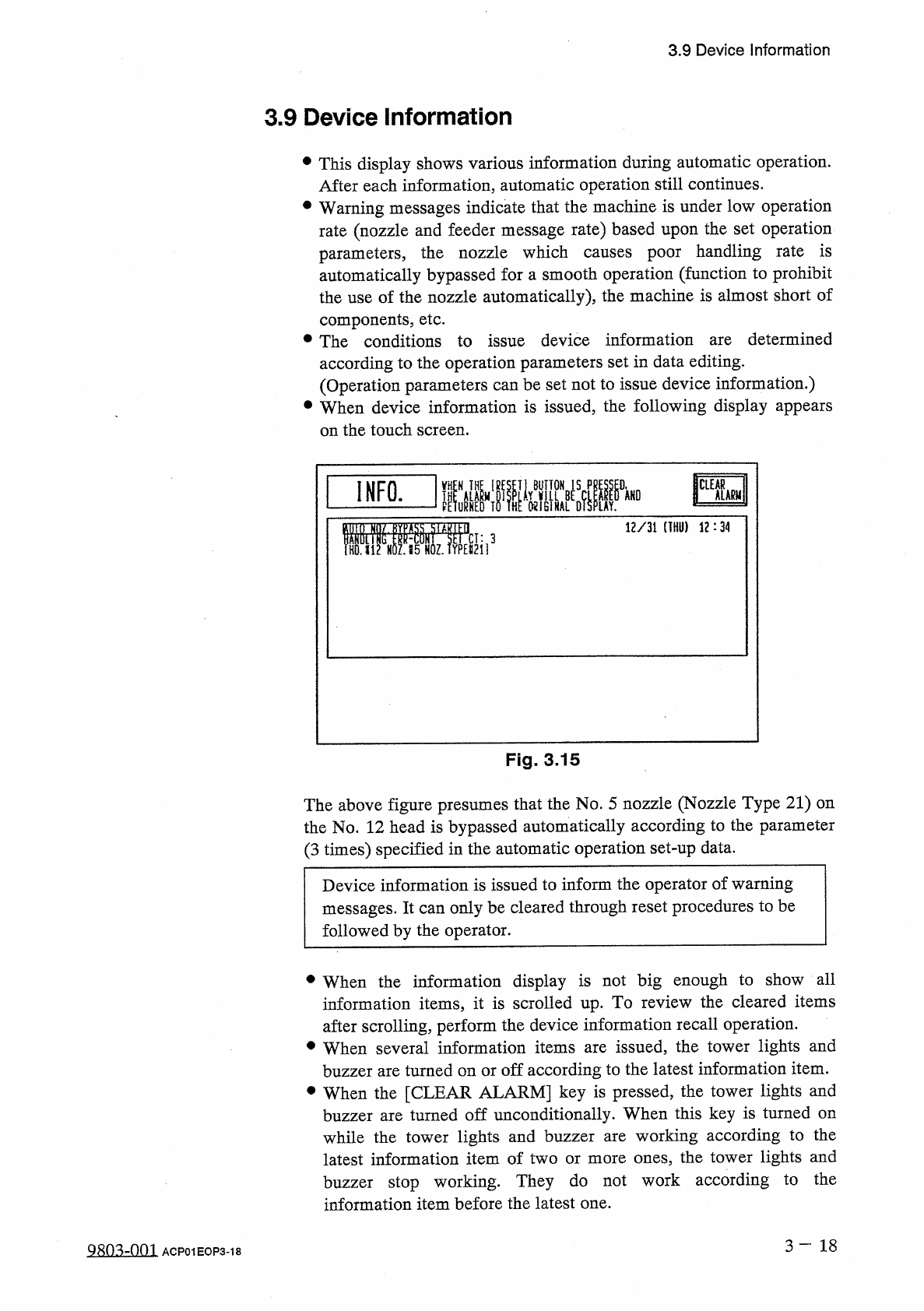
•
When
device
information
is
issued
,
the
following
display
appears
on
the
touch
screen
.
determined
are
INFO
.
12
/
31
(
THU
)
12
:
34
Fig
.
3.15
The
above
figure
presumes
that
the
No
.
5
nozzle
(
Nozzle
Type
21
)
on
the
No
.
12
head
is
bypassed
automatically
according
to
the
parameter
(
3
times
)
specified
in
the
automatic
operation
set
-
up
data
.
Device
information
is
issued
to
inform
the
operator
of
warning
messages
.
It
can
only
be
cleared
through
reset
procedures
to
be
followed
by
the
operator
.
•
When
the
information
display
is
not
big
enough
to
show
all
information
items
,
it
is
scrolled
up
.
To
review
the
cleared
items
after
scrolling
,
perform
the
device
information
recall
operation
.
•
When
several
information
items
are
issued
,
the
tower
lights
and
buzzer
are
turned
on
or
off
according
to
the
latest
information
item
.
•
When
the
[
CLEAR
ALARM
]
key
is
pressed
,
the
tower
lights
and
buzzer
are
turned
off
unconditionally
.
When
this
key
is
turned
on
while
the
tower
lights
and
buzzer
latest
information
item
of
two
or
more
ones
,
the
tower
lights
and
buzzer
stop
working
.
They
do
not
work
according
to
the
information
item
before
the
latest
one
.
working
according
to
the
are
3
-
1 8
9803
-
001
ACP
01
EOP
3
-
18
3.9
Device
information
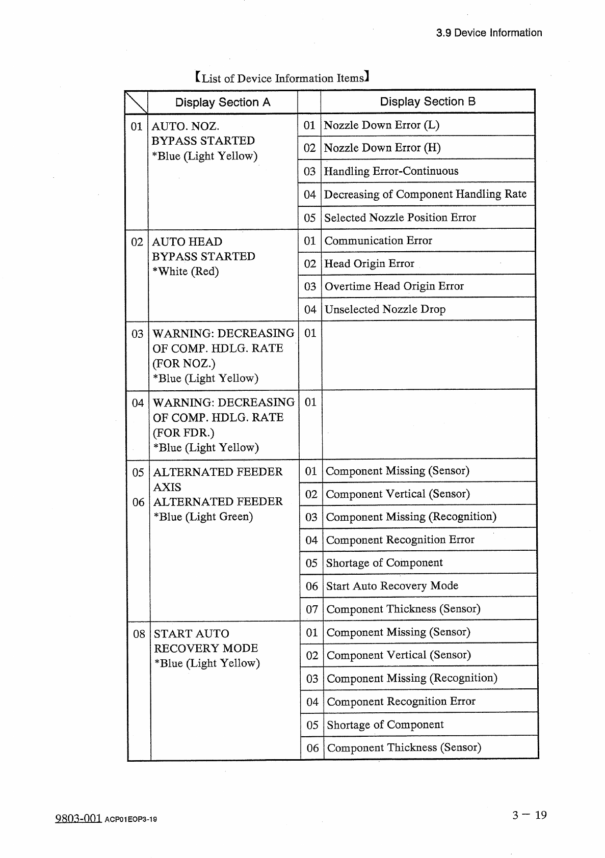
【
List
of
Device
Information
Items
】
Display
Section
B
Display
Section
A
01
Nozzle
Down
Error
(
L
)
01
AUTO
.
NOZ
.
BYPASS
STARTED
*
Blue
(
Light
Yellow
)
Nozzle
Down
Error
(
H
)
02
Handling
Error
-
Continuous
03
Decreasing
of
Component
Handling
Rate
04
Selected
Nozzle
Position
Error
05
01
Communication
Error
02
AUTO
HEAD
BYPASS
STARTED
*
White
(
Red
)
Head
Origin
Error
02
Overtime
Head
Origin
Error
03
Unselected
Nozzle
Drop
04
03
WARNING
:
DECREASING
OF
COMP
.
HDLG
.
RATE
(
FOR
NOZ
.
)
*
Blue
(
Light
Yellow
)
01
04
WARNING
:
DECREASING
HDLG
.
RATE
01
OF
COMP
.
]
(
FOR
FDR
.
)
*
Blue
(
Light
Yellow
)
Component
Missing
(
Sensor
)
01
05
ALTERNATED
FEEDER
AXIS
ALTER
*
Blue
(
Light
Green
)
Component
Vertical
(
Sensor
)
02
NATED
FEEDER
06
Component
Missing
(
Recognition
)
03
Component
Recognition
Error
04
05
Shortage
of
Component
Start
Auto
Recovery
Mode
06
Component
Thickness
(
Sensor
)
07
Component
Missing
(
Sensor
)
01
08
START
AUTO
RECOVERY
MODE
*
Blue
(
Light
Yellow
)
Component
Vertical
(
Sensor
)
02
Component
Missing
(
Recognition
)
03
Component
Recognition
Error
04
Shortage
of
Component
05
Component
Thickness
(
Sensor
)
06
3
-
1 9
Qso
^
-
nm
ACP
01
EOP
3
-
19