1OPERATION_.pdf - 第111页
2.6 Program Change ( 2 ) Hole Reference Positioning Pin PI Positioning Pin Q 1 Guide Plate 「 飞二 ] ' r - i O O O O O O O O O O O O O O O O O O O 0 . 0 OIQQ ^ O O O O O O O O O O O O O 0 ° O 縱 0 嫩 0 X 0 » ° o ° ° o ° …
2.6
Program
Change
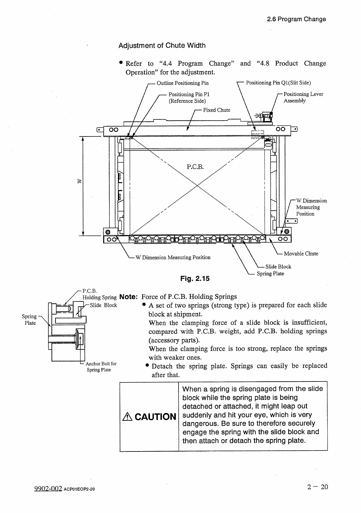
Adjustment
of
Chute
Width
•
Refer
to
“
4.4
Program
Change
”
and
“
4.8
Product
Change
Operation
”
for
the
adjustment
.
Outline
Positioning
Pin
Positioning
Pin
Ql
(
Slit
Side
)
Positioning
Pin
PI
(
Reference
Side
)
Positioning
Lever
Assembly
Fixed
Chute
OO
3
E
:
OO
r
-
:
=
i
P
.
C
.
B
.
5
-
W
Dimension
Measuring
Position
HD
j
®
mmsmmsm
OO
Movable
Chute
W
Dimension
Measuring
Position
Slide
Block
Spring
Plate
Fig
.
2.15
P
.
C
.
B
.
Holding
Spring
Note
:
Force
of
P
.
C
.
B
.
Holding
Springs
•
A
set
of
two
springs
(
strong
type
)
is
prepared
for
each
slide
block
at
shipment
.
When
the
clamping
force
of
a
slide
block
is
insufficient
,
compared
with
P
.
C
.
B
.
weight
,
add
P
.
C
.
B
.
holding
springs
(
accessory
parts
)
.
When
the
clamping
force
is
too
strong
,
replace
the
springs
with
weaker
ones
.
•
Detach
the
spring
plate
.
Springs
after
that
.
Slide
Block
Spring
Plate
C
Anchor
Bolt
for
Spring
Plate
easily
be
replaced
can
When
a
spring
is
disengaged
from
the
slide
block
while
the
spring
plate
is
being
detached
or
attached
,
it
might
leap
out
suddenly
and
hit
your
eye
,
which
is
very
dangerous
.
Be
sure
to
therefore
securely
engage
the
spring
with
the
slide
block
and
then
attach
or
detach
the
spring
plate
.
A
CAUTION
2
-
20
QQ
02
-
002
ACP
01
EOP
2
-
20
2.6
Program
Change
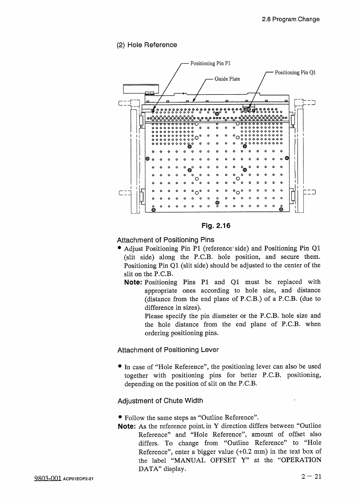
(
2
)
Hole
Reference
Positioning
Pin
PI
Positioning
Pin
Q
1
Guide
Plate
「
飞二
]
'
r
-
i
O O O O OO O O O O O O O O O O O O O
0 . 0
OIQQ
^
O O O O O O O O O O
O
O
O
0
°
O
縱
0
嫩
0
X
0
»
°
o
°
°
o
°
。
八
。
。
嫩
—
oo
ooo
6
6
6
'
0
O o o o o o o o o o b d
6
6
6
6
O
o
6
o
0 0 0 0 0 0 0 0 0 0 0
^
0
O
O
O
O
0 00 00 0 00 00 0
*
^
*
^
o
o
o
o
o
o
o
o
o
©
@
o o o o o o o o o o o
o o o o o o o o o o o
o o o o o o o o o
o o o o o o o o o
o
o
o
o
©
®
o
o
O
O
0
O
O
O
o
O
O
O
o
O
O
o
o
o
o
o
o
o
o
o
o
o
o
o
o
o
a
°
°
°
o
°
0
°
0
°
o
°
°
°
r
二
3
匚
=
口
o
o
o
o
o
ooo
@
0
^
0 0 0
Fig
.
2.16
Attachment
of
Positioning
Pins
•
Adjust
Positioning
Pin
PI
(
reference
1
side
)
and
Positioning
Pin
Q
1
(
slit
side
)
along
the
P
.
C
.
B
.
hole
position
,
and
Positioning
Pin
Q
1
(
slit
side
)
should
be
adjusted
to
the
center
of
the
slit
on
the
P
.
C
.
B
.
them
.
secure
Note
:
Positioning
Pins
PI
and
Q
1
must
be
replaced
with
according
to
hole
size
,
and
distance
appropriate
(
distance
from
the
end
plane
of
P
.
C
.
B
.
)
of
a
P
.
C
.
B
.
(
due
to
difference
in
sizes
)
.
Please
specify
the
pin
diameter
or
the
P
.
C
.
B
.
hole
size
and
the
hole
distance
from
the
end
plane
of
P
.
C
.
B
.
when
ones
ordering
positioning
pins
.
Attachment
of
Positioning
Lever
•
In
case
of
“
Hole
Reference
”
,
the
positioning
lever
can
also
be
used
together
with
positioning
pins
for
better
P
.
C
.
B
.
positioning
,
depending
on
the
position
of
slit
on
the
P
.
C
.
B
.
Adjustment
of
Chute
Width
•
Follow
the
same
steps
as
“
Outline
Reference
”
.
Note
:
As
the
reference
point
in
Y
direction
differs
between
“
Outline
Reference
”
and
“
Hole
Reference
’
’
,
amount
of
offset
also
differs
.
To
change
from
“
Outline
Reference
”
to
“
Hole
Reference
”
,
enter
a
bigger
value
(
十
0.2
mm
)
in
the
text
box
of
the
label
“
MANUAL
OFFSET
Y
”
at
the
“
OPERATION
DATA
”
display
.
2
—
21
QRO
^
-
Om
ACP
01
EOP
2
-
21
2.6
Program
Change
(
3
)
Adjustment
of
P
.
C
.
B
.
Support
Pins
Turn
off
power
to
the
machine
before
adjustment
to
protect
your
hands
from
moving
mechanisms
.
A
CAUTION
When
P
.
C
.
B
.
size
is
changed
or
some
components
placed
on
the
back
of
P
.
C
.
B
.
,
positions
of
P
.
C
.
B
.
support
pins
must
also
be
changed
.
previously
are
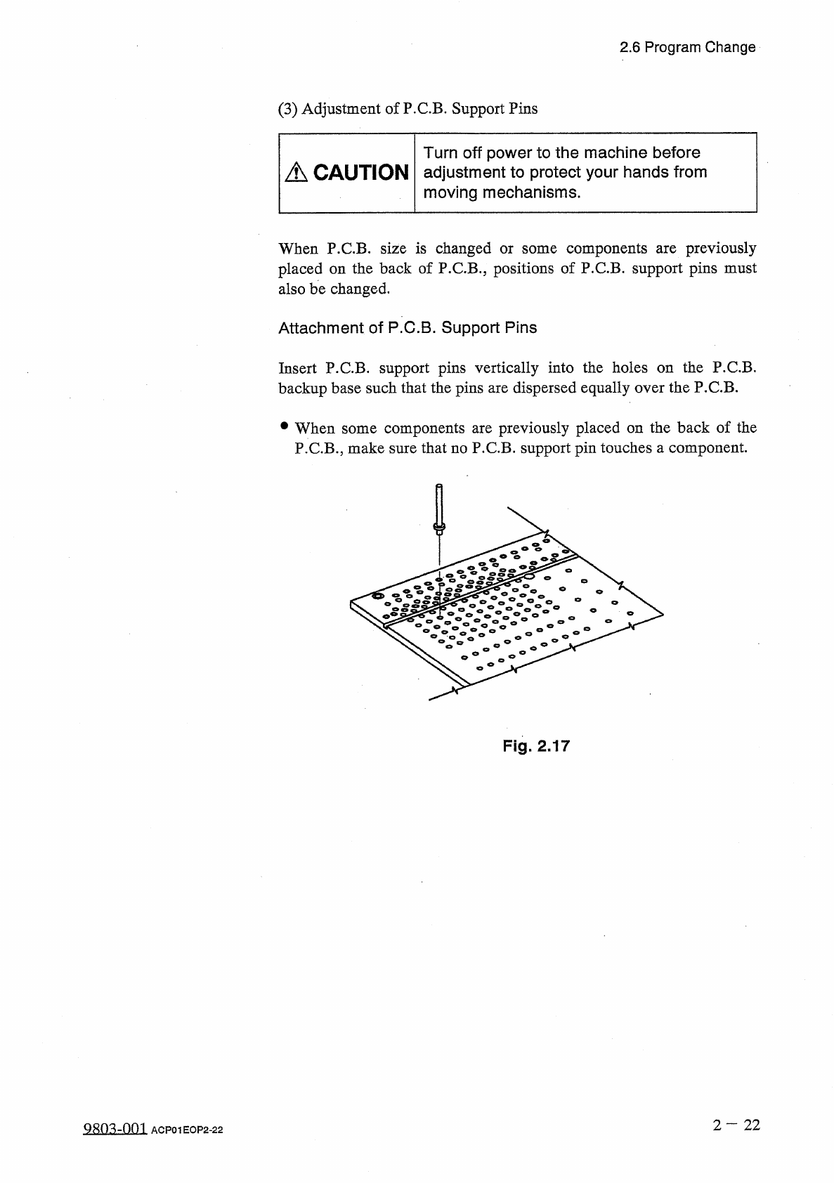
Attachment
of
P
.
C
.
B
.
Support
Pins
Insert
P
.
CB
.
support
pins
vertically
into
the
holes
on
the
P
.
C
.
B
.
backup
base
such
that
the
pins
are
dispersed
equally
over
the
P
.
C
.
B
.
components
are
previously
placed
on
the
back
of
the
P
.
C
.
B
.
,
make
sure
that
no
P
.
C
.
B
.
support
pin
touches
a
component
.
參
When
some
Fig
.
2.17
2
—
22
QR
03
-
001
ACP
01
EOP
2
-
22