1OPERATION_.pdf - 第250页
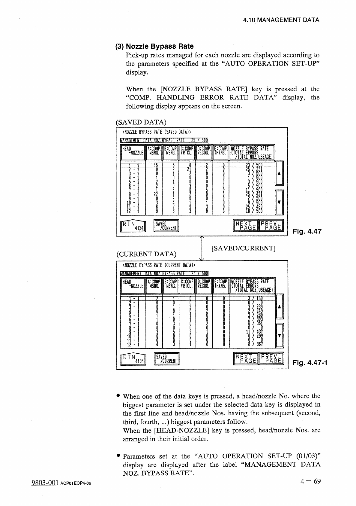
4.10 MANAGEMENT DATA ( 3 ) Nozzle Bypass Rate Pick - up rates managed for each nozzle are displayed according to the parameters specified at the “ AUTO OPERATION SET - UP ” display . When the [ NOZZLE BYPASS RATE ] key i…
4
,
10
MANAGEMENT
DATA
•
When
the
[
SAVED
/
CURRENT
]
key
is
pressed
,
the
“
NOZZLE
MESSAGE
RATE
(
SAVED
DATA
)
”
display
disappears
and
the
“
NOZZLE
MESSAGE
RATE
(
CURRENT
DATA
)
”
appears
vice
versa
.
The
“
NOZZLE
MESSAGE
RATE
(
SAVED
DATA
)
”
display
shows
parameters
calculated
just
before
the
current
ones
.
The
“
NOZZLE
MESSAGE
RATE
(
CURRENT
DATA
)
,
,
display
shows
parameters
being
calculated
at
present
.
or
[
MANAGEMENT
DATA
NOZ
.
MESSAGE
RATE
X
/
XX
]
in
Figs
.
4.46
and
4.46
-
1
.
MANAGEMENT
DATA
NOZ
.
MESSAGE
RATE
5
/
50
:
Numerator
5
shows
the
number
of
pick
-
up
errors
detected
before
50
components
components
detected
,
a
message
appears
in
the
text
boxes
of
the
label
“
MGT
.
INFO
.
”
,
indicating
that
the
pick
-
up
rate
has
deteriorated
.
When
the
number
of
pick
-
up
errors
does
not
reach
“
5
”
after
50
components
are
picked
up
,
XX
/
XX
is
reset
to
“
00
/
00
”
and
counting
starts
again
.
The
“
NOZZLE
MESSAGE
RATE
(
SAVED
DATA
)
”
shows
the
parameters
just
before
this
delimiter
.
picked
up
.
to
be
picked
up
.
When
5
pick
-
up
Denominator
50
shows
that
50
are
errors
are
are
•
When
an
alarm
is
issued
,
the
blue
head
/
nozzle
No
.
turns
red
at
the
“
NOZZLE
MESSAGE
RATE
(
SAVED
DATA
)
,
,
display
.
4
一
68
ACP
01
EOP
4
-
68
4.10
MANAGEMENT
DATA
(
3
)
Nozzle
Bypass
Rate
Pick
-
up
rates
managed
for
each
nozzle
are
displayed
according
to
the
parameters
specified
at
the
“
AUTO
OPERATION
SET
-
UP
”
display
.
When
the
[
NOZZLE
BYPASS
RATE
]
key
is
pressed
at
the
“
COMP
.
HANDLING
ERROR
RATE
DATA
”
display
,
the
following
display
appears
on
the
screen
.
(
SAVED
DATA
)
〈
NOZZLE
BYPASS
RATE
(
SAVED
_
>
BMEBEHEMS
EOMSOHE
/
bOM
C
:
C
0
MP
.
1
»
RATE
B
:
C
0
MP
鼷
.
HEAD
A
:
C
0
MP
M
5
NG
.
VRTCL
.
-
NOZZLE
MSNG
.
n
f
21
i
5
-
1
11
/
2
;
!
25
/
1
4
1
7
扣
1
il
-
1
6
SAVED
/
CURRENI
Fig
.
4.47
[
SAVED
/
CURRENT
]
(
CURRENT
DATA
)
<
N
0
ZZLE
BYPASS
RATE
(
CURRENT
DATA
)
>
MANfltihMhNt
UAIA
曲
/
.
fWlM
沾 以
It
:
TOT
m
譽
i
=
W
:
ir
Aff
HEAD
-
NOZZLE
E
)
~
rm
i
i
8
2
0
0
0
0
0
0
0
i
0
1
-
1
0
/
36
;
3
0
-
1
11
/
-
1
10
M
11
-
1
12
-
1
/
367
0
4
3
臨
E
脱
N
SAVED
/
CURRENT
Fig
.
4.47
-
1
•
When
one
of
the
data
keys
is
pressed
,
a
head
/
nozzle
No
.
where
the
biggest
parameter
is
set
under
the
selected
data
key
is
displayed
in
the
first
line
and
head
/
nozzle
Nos
.
having
the
subsequent
(
second
,
third
,
fourth
,
..
.
)
biggest
parameters
follow
.
When
the
[
HEAD
-
NOZZLE
]
key
is
pressed
,
head
/
nozzle
Nos
.
arranged
in
their
initial
order
.
are
•
Parameters
set
at
the
“
AUTO
OPERATION
SET
-
UP
(
01
/
03
)
”
displayed
after
the
label
“
MANAGEMENT
DATA
display
NOZ
.
BYPASS
RATE
”
.
are
4
一
69
mn
=
m
ACP
01
EOP
4
-
69
4.10
MANAGEMENT
DATA
•
When
the
[
SAVED
/
CURRENT
]
key
is
pressed
,
the
“
NOZZLE
BYPASS
RATE
(
SAVED
DATA
)
,
,
display
disappears
and
the
“
NOZZLE
BYPASS
RATE
(
CURRENT
DATA
)
,,
appears
or
vice
versa
.
The
“
NOZZLE
BYPASS
RATE
(
SAVED
DATA
)
”
display
shows
parameters
calculated
just
before
the
current
ones
.
The
“
NOZZLE
BYPASS
RATE
(
CURRENT
DATA
)
”
display
shows
parameters
being
calculated
at
present
.
[
MANAGEMENT
DATA
NOZ
.
BYPASS
RATE
XX
/
XX
]
in
Figs
.
4.47
and
4.47
-
1
MANAGEMENT
DATA
NOZ
.
BYPASS
RATE
25
/
500
:
Numerator
25
shows
the
number
of
pick
-
up
errors
detected
before
500
components
are
picked
up
.
Denominator
500
shows
that
500
components
are
to
be
picked
up
.
When
25
pick
-
up
detected
,
a
message
appears
in
the
text
boxes
of
the
label
“
MGT
.
INFO
,
”
,
indicating
that
the
pick
-
up
rate
has
deteriorated
and
the
nozzle
is
automatically
bypassed
.
When
the
number
of
pick
-
up
errors
does
not
reach
“
25
”
after
500
components
are
picked
up
,
XX
/
XX
is
reset
to
“
00
/
00
”
and
counting
starts
again
.
The
“
NOZZLE
BYPASS
RATE
(
SAVED
DATA
)
”
shows
the
parameters
just
before
this
delimiter
.
errors
are
•
When
a
nozzle
is
automatically
bypassed
,
the
blue
head
/
nozzle
No
.
turns
red
at
the
“
NOZZLE
BYPASS
RATE
(
SAVED
DATA
)
”
display
.
4
一
70
Q
^
-
001
ACP
01
EOP
4
-
70