1OPERATION_.pdf - 第269页
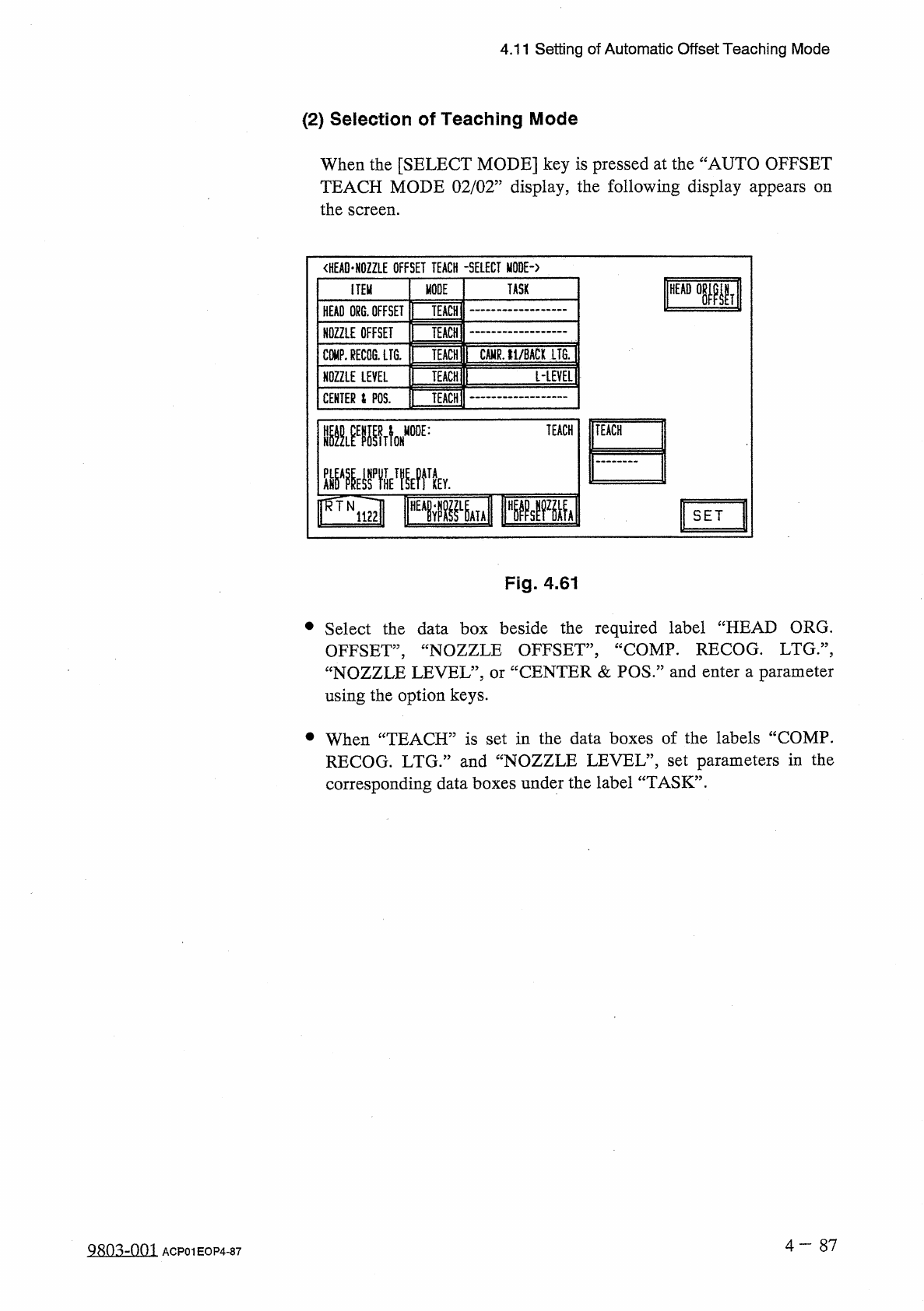
4.11 Setting of Automatic Offset Teaching Mode ( 2 ) Selection of Teaching Mode When the [ SELECT MODE ] key is pressed at the “ AUTO OFFSET TEACH MODE 02 / 02 ” display , the following display appears the screen . on &l…
4.11
Setting
of
Automatic
Offset
Teaching
Mode
(
1
)
Editing
of
Specified
Parameters
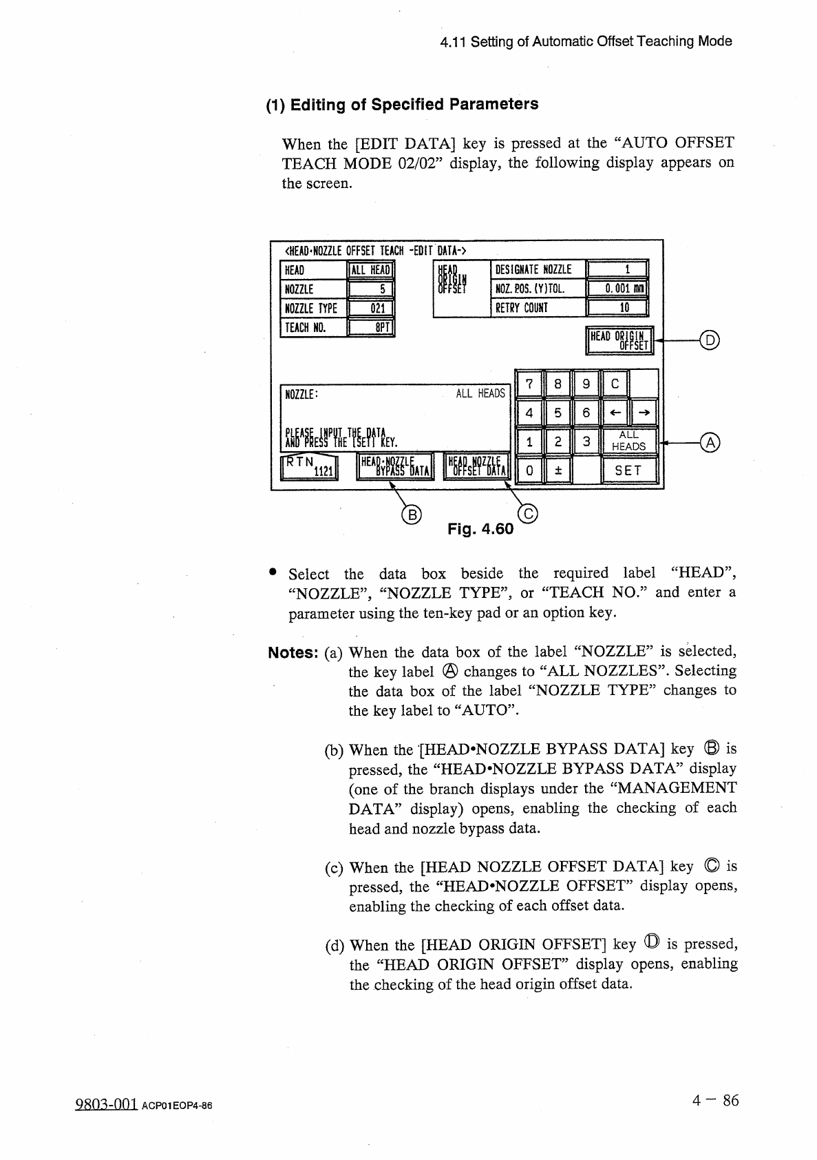
When
the
[
EDIT
DATA
]
key
is
pressed
at
the
“
AUTO
OFFSET
TEACH
MODE
02
/
02
”
display
,
the
following
display
appears
on
the
screen
.
<
HEA
0
*
N
0
ZZLE
OFFSET
TEACH
-
EDIT
DATA
-
)
ALL
HEADI
DESIGNATE
NOZZLE
HEAD
Ilf
N
0
Z
.
P
0
S
.
(
YITOL
.
0.001
HH
1
NOZZLE
5
RETRY
COUNT
10
NOZZLE
TYPE
021
ID
TEACH
HO
.
<
§
)
HEAD
IN
SET
8
C
7
9
ALL
HEADS
NOZZLE
:
5
6
4
腿
yiwk
ALL
o
2
3
1
HEADS
o
SET
±
®
Fig
.
4.60
®
•
Select
the
data
box
beside
the
required
label
“
HEAD
”
,
“
NOZZLE
,
,
,
“
NOZZLE
TYPE
,
,
,
parameter
using
the
ten
-
key
pad
or
an
option
key
.
TEACH
NO
.
”
and
enter
a
or
Notes
:
(
a
)
When
the
data
box
of
the
label
“
NOZZLE
”
is
selected
,
the
key
label
@
changes
to
“
ALL
NOZZLES
”
.
Selecting
the
data
box
of
the
label
“
NOZZLE
TYPE
”
changes
to
the
key
label
to
“
AUTO
”
.
(
b
)
When
the
[
HEAD
-
NOZZLE
BYPASS
DATA
]
key
©
is
display
the
“
HEAD
-
NOZZLE
BYPASS
DATA
5
pressed
,
(
one
of
the
branch
displays
under
the
“
MANAGEMENT
DATA
”
display
)
opens
,
enabling
the
checking
of
each
head
and
nozzle
bypass
data
.
(
c
)
When
the
[
HEAD
NOZZLE
OFFSET
DATA
]
key
©
is
pressed
,
the
“
HEAJ
>
NOZZLE
OFFSET
”
display
opens
,
enabling
the
checking
of
each
offset
data
.
(
d
)
When
the
[
HEAD
ORIGIN
OFFSET
]
key
◎
is
pressed
,
the
“
HEAD
ORIGIN
OFFSET
”
display
opens
,
enabling
the
checking
of
the
head
origin
offset
data
.
4
—
8 6
Q
80
^
-
nm
ACP
01
EOP
4
-
86
4.11
Setting
of
Automatic
Offset
Teaching
Mode
(
2
)
Selection
of
Teaching
Mode
When
the
[
SELECT
MODE
]
key
is
pressed
at
the
“
AUTO
OFFSET
TEACH
MODE
02
/
02
”
display
,
the
following
display
appears
the
screen
.
on
<
HEAD
-
HOZZLE
OFFSET
TEACH
-
SELECT
MODE
-
〉
MODE
TASK
ITEM
TEACH
:
HEAD
ORG
.
OFFSET
TEACH
NOZZLE
OFFSET
CAMR
.
11
/
BACK
LTG
.
COMP
.
RECOG
.
LFG
.
TEACH
[
-
LEVEL
1
TEACH
NOZZLE
LEVEL
TEACH
CENTER
i
POS
.
TEACH
mmA
MODE
:
IFWiml
FPPM
r
^
TN
SET
Fig
.
4.61
•
Select
the
data
box
beside
the
required
label
“
HEAD
ORG
.
OFFSET
,
,
,
“
NOZZLE
OFFSET
”
,
“
COMP
.
RECOG
.
LTG
:
\
“
NOZZLE
LEVEL
”
,
or
“
CENTER
&
POS
”
and
enter
a
parameter
using
the
option
keys
.
•
When
“
TEACH
”
is
set
in
the
data
boxes
of
the
labels
“
COMP
.
RECOG
.
LTG
.
”
and
“
NOZZLE
LEVEL
”
,
set
parameters
in
the
corresponding
data
boxes
under
the
label
“
TASK
”
.
4
-
87
ACP
01
EOP
4
-
87
4.12
Warm
-
Up
Running
Mode
Set
4.12
Warm
-
Up
Running
Mode
Set
Simplifying
the
warm
-
up
running
operation
reduces
the
changes
in
temperature
(
deterioration
with
age
)
around
the
DD
head
and
the
rotary
turret
,
stabilizing
and
improving
the
accuracy
of
component
placement
.
Note
:
The
automatic
teaching
function
belongs
to
this
function
as
a
supporting
one
.
Restrictions
of
Warm
-
Up
Running
Mode
(
1
)
This
function
works
in
the
“
TEST
”
mode
regardless
of
the
test
mode
settings
at
the
“
TEST
MODE
”
display
.
(
2
)
The
SIF
function
does
not
work
.
(
3
)
The
trash
box
fill
-
up
warning
function
does
not
work
.
(
4
)
The
maintenance
warning
function
does
not
work
.
(
5
)
The
automatic
teaching
function
does
not
work
.
(
6
)
The
same
restrictions
as
those
in
the
normal
running
mode
applies
to
the
ET
communication
.
(
7
)
The
warm
-
up
running
time
is
added
as
“
TEST
MODE
TIME
”
at
the
“
MANAGEMENT
DATA
”
display
.
Starting
the
Warm
-
Up
Running
Operation
(
1
)
Activate
the
machine
in
the
dry
-
cycle
mode
according
to
the
current
pattern
program
.
The
machine
does
not
perform
any
component
picks
,
component
placement
operation
,
P
.
C
.
B
.
transfer
operation
,
etc
.
,
at
all
.
As
the
machine
performs
a
transfer
operation
in
the
dry
-
cycle
mode
,
it
is
required
to
remove
the
P
.
C
.
B
.
’
s
from
the
transfer
section
and
the
X
/
Y
table
.
It
is
recommended
that
an
exclusive
pattern
program
for
the
warm
-
up
running
operation
be
prepared
for
better
efficiency
.
(
2
)
The
“
OPN
.
MODE
”
display
stays
active
during
the
running
operation
.
For
safety
purposes
,
any
operations
at
a
display
during
the
warm
-
up
running
operation
.
Once
the
machine
is
set
in
the
“
STOP
”
mode
,
another
display
can
be
opened
.
warm
-
up
prohibited
are
(
3
)
This
function
works
for
the
period
of
time
specified
in
the
menu
.
4
-
88
0107
-
001
ACP
01
EOP
4
-
88