3_AVS-V2_MCT-UM-internal_EN_07-2019.pdf - 第13页
ASM AVS - U SER M ANUAL P AGE 13 OF 182 Whe n mov ing acro ss t he plat e, th e s peed must not be red uced an d of c our se, t he m oveme nt can not be s top ped. The spr ay s hou ld be a pplie d eve nly a nd s ligh tly…
ASM AVS - USER MANUAL
PAGE 12 OF 182
2.1.3.1.2 Preparing the glass plate:
NOTICE
2TUse the spray mount glue instead of double sided gluing foil
We recommend "3M Spray Mount 400ml" [03071372-01] instead of double-sided adhesive sheet to use.
The spray does not wear as fast as the film. When scraping there are substantially fewer streaks.
You can use the drive up to 50 times.
NOTICE
Scraping the components
The components can be gently scraped off after the measurement of the plate.
Several (up to 50) configurations / measurements can thus be performed with a film.
Caution!!
The dot grid (3) is not glued on the film and thus not protected!
When scraping therefore always from the point grid (3) proceed away to push the components not on the
dot grid!
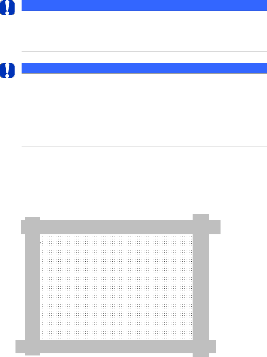
Do not forget, before applying the spray adhesive, to cover the edges of the plate with an ad-
hesive tape (eg: "adhesive tape Tesa 4657 30 mm wide" [00306789-01]), as shown below in the
image.
This is first, not to contaminate the metal frame, which is indeed guided by the PCB and sec-
ondly, in order not to cover the "global fiducials".
Please refer to the so-called. "Stop lines" (see picture on page 14).
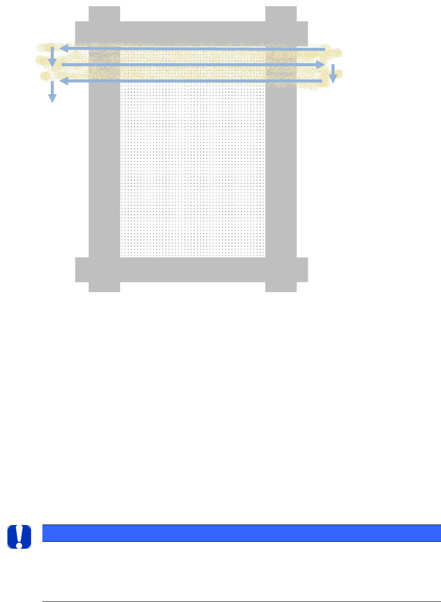
Cover the environment below the plate with big paper towels (also newsprint) or films made.
Move the spray at a constant speed, in about 20cm distance from the plate, over the entire
width of the plate.
Start the movement outside of the plate.
ASM AVS - USER MANUAL
PAGE 13 OF 182
When moving across the plate, the speed must not be reduced and of course, the movement
cannot be stopped.
The spray should be applied evenly and slightly.
Do not apply too much!
Then, remove the adhesive tapes from the borders again.
2.1.3.1.3 Cleaning the glass plate:
To remove the spray adhesive from the plate is best to use the recommended
"3M aerosol cleaners on lime basis" [03071373-01], or “Adhesive remover preset wipes, tub”
[03126751-01] from DEK.
Bring the cleaner evenly on the plate on and leave it min. 3 min. act.
After that you can wipe the soggy spray with cloths.
For further purification use ethanol (alcohol) which should be available in every SMT
manufacturing.
Finally, you can clean the glass plate on both sides with glass cleaner without leaving streaks.
NOTICE
No Ethanol (alcohol) when measuring printers with glue!
Do not use ethanol or other alcohol to clean the plates when measuring screen printers!
The alcohol allows the adhesive to cure in seconds and thus also changes the shape of the adhesive points.
ASM AVS - USER MANUAL
PAGE 14 OF 182
2.1.3.2 Measurement components:
When considering the measurement components (or measurement dummies), it is necessary
to distinguish between the applications (machine configuration) for which a component is to
be used.
2.1.3.2.1 Cerampads 2x2mm on tape 00359505-01:
Used for machines or heads which are operated in Collect&Place mode and are primarily used
for the placement of chip components.
Ceramic pads are supplied under item number 00359505-01 in reels of 5000.
2.1.3.2.2 Standard SMD chip components (0201, 0402,…..):
For machines or heads that are operated in Collect&Place mode.
It is also possible to use conventional SMD chip components instead of ceramic pads. Howev-
er, these are of questionable value for MCT purposes since they are usually of worse quality
(tolerance of edge widths and lengths etc.).
CAUTION
2TDanger of wrong interpretation of the measured results!
These components should not be used until the underlying machine capability has been
demonstrated using the preferred MCT components.
2.1.3.2.3 Glass components CC02-005:
SIPLACE machines with an analog vision system possessed a fine calibration option. Glass
components (CC02-005) and other items were supplied for this fine calibration. These can al-
so be used for MCA’s for C&P 6-segment heads, resp. at all P&P heads, as an alternative.
00343702-01 glass components RV-K.6/12/IC-K.(CC02-005) with tray.
This demands the use of a tray holder, item No. 00116430-01.
2.1.3.2.4 Glass components GC AC 01, GC AC 02 und GC AC 03:
The following applies to all 3 components:
• The QFP or BGA structure is optically centered using the placement unit's component
camera.
• The solder bumps help maintain the required distance so that the glass components are
not placed across the entire area of the adhesive film.
• ASM AVS optically centers the measurement fiducials through the 0.2 mm thick glass layer
in the component pocket holes and thus calculates the position of the components relative
to the position of the fiducial on the board.
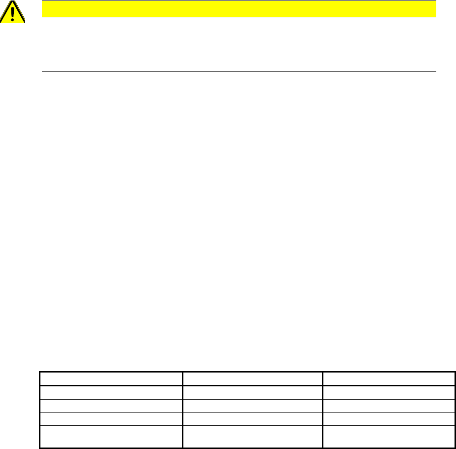
2.1.3.2.5 Overview of components:
Head
Component (standard)
component (alternative)
CP-12, CP-20, CPP (12) heads
Cerampads
GC AC 01 (BGA_DCA); SMD Chips
6er
GC AC 01 (QFP)
CC002-005
IC-Head, Twin-Head, P&P-Modul, CPP (1)
GC AC 02 (QFP) (BGA at FC-Cam.)
GC AC 01 (QFP); CC002-005
4times measurement on Twin, IC Head and
P&P-Modul
GC AC 03