3_AVS-V2_MCT-UM-internal_EN_07-2019.pdf - 第179页
ASM AVS - U SER M ANUAL P AGE 179 OF 182 If, ho wever , me asurem ent is per forme d r ow- by -row wit hout any cha nge in di rec tion , t he glo bal tren d o f the i ndivi dual v al ues is ov erl aid by a fur the r tre …
ASM AVS - USER MANUAL
PAGE 178 OF 182
NOTICE
The sequence of the measurement is fully reflected in the "Single Value Chart". You should therefore take
into account the measurement sequence when interpreting the chart.
See also 4.3.5.3.8 Adjustment of measurement sequence.
(2) Trend mapping?
When interpreting trends in particular, attention must be paid to the relationship between
the placement sequence and the measurement sequence.
Assumptions:
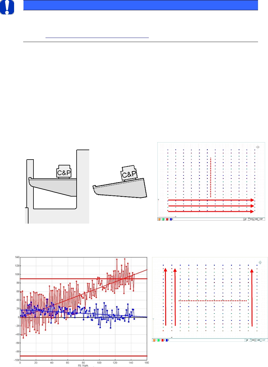
The gantry is positioned obliquely in Y.
The head has rolled over the star in X. Thus, if you view the board from above, the compo-
nents were placed from lef-t to right in one head cycle.
The next head cycle follows in an upward direction.
If the measurement was performed column-by-column and without changing direction, the
result is as follows.
Portalverzug
Measuring sequence
Measuring sequence
ASM AVS - USER MANUAL
PAGE 179 OF 182
If, however, measurement is performed row-by-row without any change in direction, the
global trend of the individual values is overlaid by a further trend within a head cycle.
One could conclude from this that the segment offset on the head is not calibrated correct-
ly, but the measurement sequence in Y causes the rising value of the Y offset resulting from
the angle of the gantry to increase with every measurement in a head cycle, to then return
to the minimum value at segment 1 (left).
This results in a saw-tooth pattern.
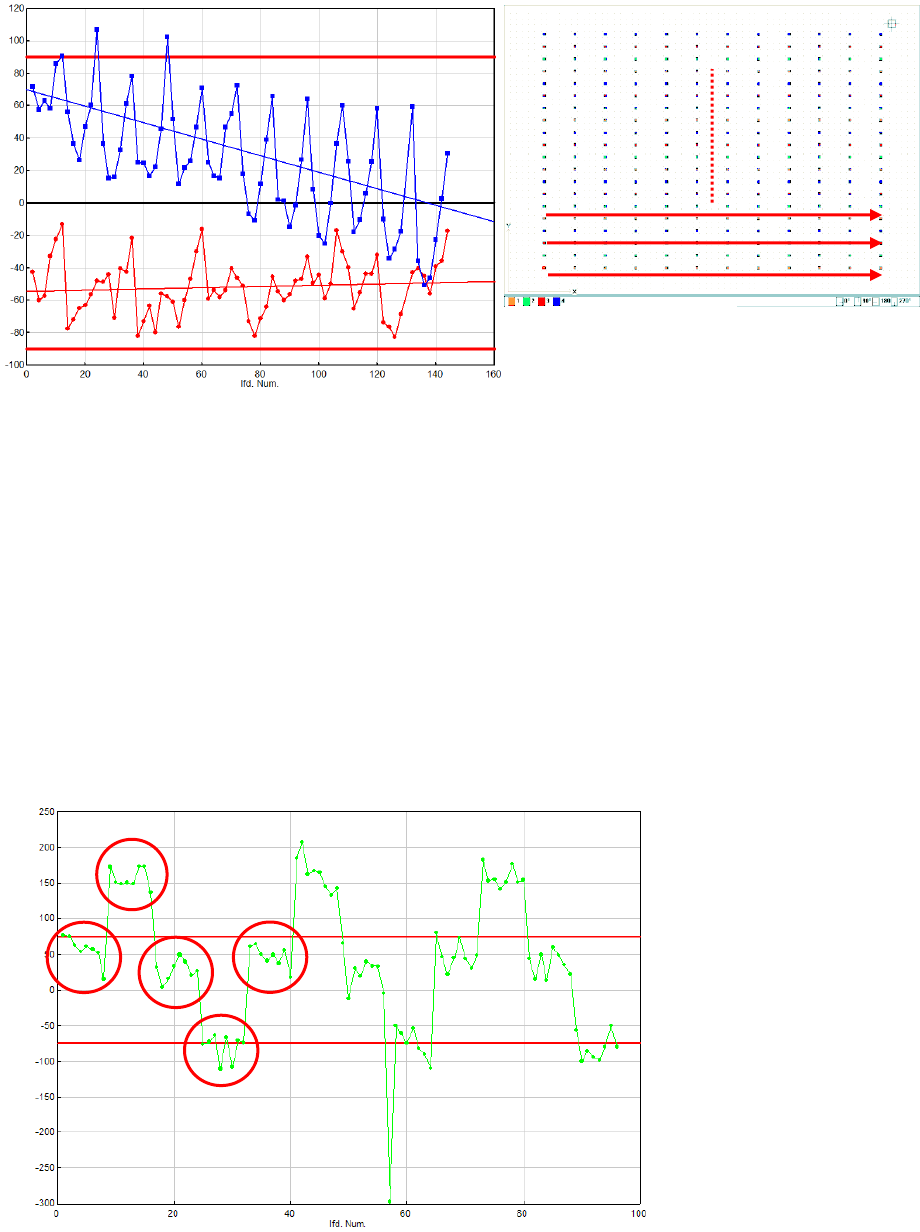
(3) Trend for a segment offset?
The chart below shows a typical curve for a segment offset on a 12-segment C&P head.
The groups of individual measurements placed by one segment can be clearly seen. An "out-
lier" can also clearly be seen on segment 8.
Measuring sequence

ASM AVS - USER MANUAL
PAGE 180 OF 182
7.5 How to measure glueing machine
The MCA-measurement starts with head 3.
The mode must be put on 3 for these steps in the characteristic of the used adhesive to get points
of high quality.
Head 3 and the heads 1 / 2 have to be programmed with characteristics in that way, that the pro-
gramme only can be achieved by head 3.
If the measurement and correction is completed at head 3, the characteristic lines of head 3 and
the heads 1 / 2 are going to be exchanged now, i.e. the programs can be achieved now only with
the heads 1 / 2.
a) correction on head 3:
The mean average value deviation is caused by a camera offset.
Therefore the measured value must be subtracted from the given offset of camera 1 in the "re-
al.ma".
See table above.
b) Korrektur Kopf 1 / 2:
The mean average value deviation is caused by a head offset.
For each head in the "real.ma" a minimal (position 1) and a maximum (position 2) head offset ex-
ists. The measured mean average value deviation for each head has to be add to the head offsets.
Die Bestückgenauigkeit wird für Kleberköpfe 1 und 2
gemeinsam und für den Kleberkopf 3 separat nach-
gewiesen.
The placement accuracy will be verified for
dispenser head 1 and 2 together and separate
for dispenser head 3.
Klebeparameter / dispensing parameters :
Klebertyp * / glue type *
Heraeus PD922
Heraeus PD86-002
Dosierstufe / dispensing level
1
1
Viskozahl / visco number
0
0
Temperatur / temperature
33°C
30°C
Dosierdüse / dispenser nozzle
0.44 mm
0.44 mm
Abstandhalter / spacer
0.1 mm
0.15 mm
* es kann auch ein ähnlicher Kleber benutzt werden / a similar glue type also can be used
Klebung für Einfachtransport :
Plattenabmasse : 300mm x 300mm
Anzahl Positionen : 224
Punktmatrix : 16 x 14
Punktabstand : X=10mm auf Y=10mm
Klebeprogramm : kleb_mfu.la
dispensing for single conveyor :
dimension of board : 300mm x 300mm
number of positions : 224
dot array : 16 x 14
dot distance : X=10mm by Y=10mm
dispenser program : kleb_mfu.la