3_AVS-V2_MCT-UM-internal_EN_07-2019.pdf - 第27页
ASM AVS - U SER M ANUAL P AGE 27 OF 182 3.2 Pow erin g up t he A SM AV S DANGER 2T !!! REMOVE THE TRANSPORT PROTEC T ION !!! The transport lock must be removed before s witching on the device, since the axles are powered…

ASM AVS - USER MANUAL
PAGE 26 OF 182
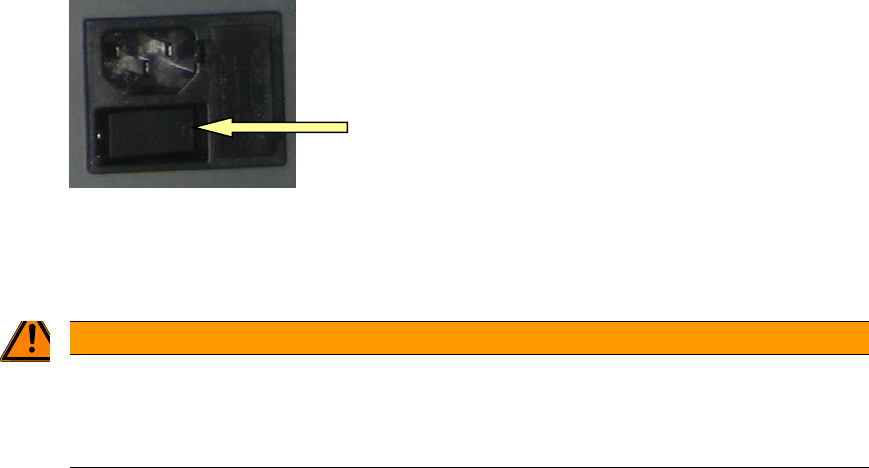
Power connection cable (power supply):
The ASM AVS is powered by means of a mains cable (for insulated devices). The power switch is
located directly beside.
LAN - Connections
ASM AVS possesses a total of 2 Ethernet LAN connections.
REMOTE_LAN is placed on the front side of the lower part and it is directly connected to the
computer.
This connection must be used for the Remote Support connection. It possesses a fixed TCP/IP
address (169.254.100.xxx) via which the computer is controlled.
At the back is the LAN connection point for SIPLACE_LAN.
Here, the network cable that connects the placement line to the customer's SIPLACE Pro or line
computer can be plugged in.
Older devices have 3 LAN ports on the back.
These are connected to a LAN switch inside the AVS device, so that all 3 connections are equiva-
lent. For older SIPLACE machines, the station computer and the machine controller (MC) can be
connected directly to the AVS and used as a machine hub.
Please also note the information on the procedure for controlling the placement line in section
5 Communication Service Notebook ASM AVS SIPLACE
ASM AVS - USER MANUAL
PAGE 27 OF 182
3.2 Powering up the ASM AVS
DANGER
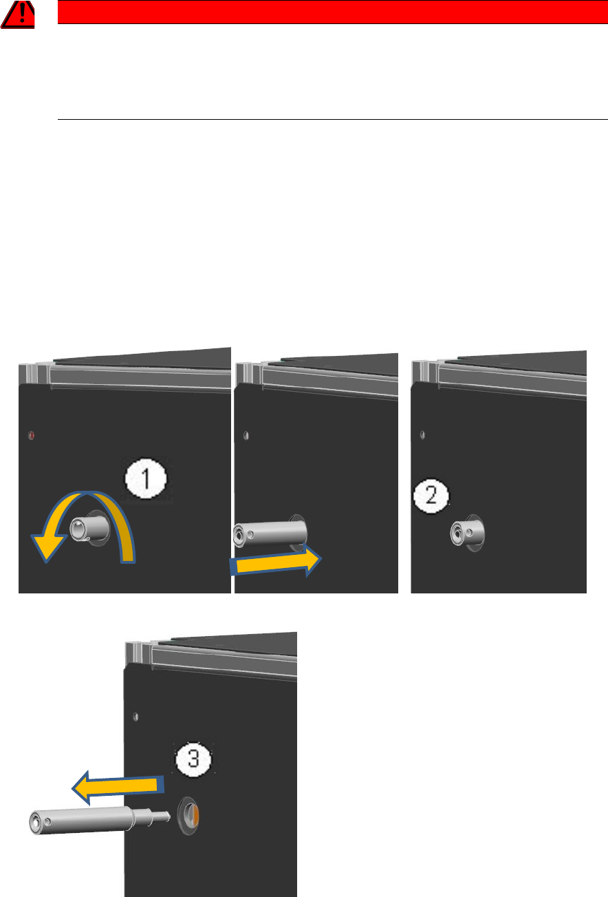
2T!!! REMOVE THE TRANSPORT PROTECTION !!!
The transport lock must be removed before switching on the device, since the axles are powered directly
by the connection of the supply voltage.
However, it is necessary to push the portal from the proximity limit switches, using the locking pin.
• Turn the transport safety pin out of the device! (1)
• If the pen is completely unscrewed from the thread, press the pen again purely to the me-
chanical stop in the device (2).
Thus, the portal will be shifted to the thread length in the middle of the unit, so that the limit
switch of the X-axis is free.
• Then remove the pin from the device. (3)
ASM AVS - USER MANUAL
PAGE 28 OF 182
• Switch on the device at the power switch.
The computer boots automatically.
The ASM AVS device has no display and control equipment (monitor, keyboard or mouse).
WARNING
2TNo connection of the AVS to the customers network
Therefore, it is not permitted, to connect the »ASM AVS« device into the customer’s network (key-
word: virus protection).
The ASM AVS is controlled via a remote desktop connection to the service engineer's notebook.
Once the ASM AVS's computer has finished booting then it is possible to establish a Remote
Support connection on the notebook via the LAN.
3.3 Shutdown of ASM AVS
As the display and the control of the ASM AVS runs via a remote desktop connection, the operat-
ing system of the computer cannot be shut down via the powered »start menu«.
Alternative 1:
Press Alt+F4 together. Now you get a dialog, in which you can select the »Shut Down« mode and
confirm with OK. Wait approx. 1 minute and then turn off the device at the power switch.
Alternative 2:
Right Mouse Click into the task bar on the bottom of the ASM AVS screen and open the »Task
manager«.
Now you can »shut down« the ASM AVS computer via the »ShutDown« menu. Wait approx. 1
minute and then turn off the device at the power switch.