3_AVS-V2_MCT-UM-internal_EN_07-2019.pdf - 第164页
ASM AVS - U SER M ANUAL P AGE 164 OF 182 7. 2.2 HOW to adj ust • X -Off_new = X-Off_old – X-Off_ measured • Y -Off_new = Y-Off_old – Y-Off_ measured • P hi-Off_new = Phi-Off_old + Phi-Off _measured NOTICE No t Stop pro d…
ASM AVS - USER MANUAL
PAGE 163 OF 182
7.2 Corrections of Offset values on DEK printers
7.2.1 WHERE to adjust?
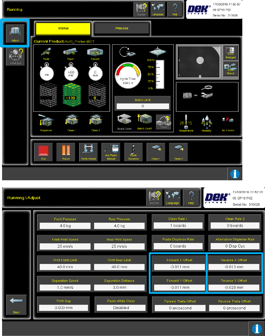
After the first plate was measured in the AVS, the captured offset values for X-, Y- and Theta,
each for both directions (back to front, front to back) can be obtained and be registered in the
printer from there.
Push the button "ADJUST" in the "Running" view, to go to the view "Running \ Adjust".

ASM AVS - USER MANUAL
PAGE 164 OF 182
7.2.2 HOW to adjust
• X-Off_new = X-Off_old – X-Off_measured
• Y-Off_new = Y-Off_old – Y-Off_measured
• Phi-Off_new = Phi-Off_old + Phi-Off_measured
NOTICE
Not Stop production run during Offset correction!
The machine reacts better to the offsets if they are entered via the ‘ADJUST’ button, during the run. If the
machine is stopped to enter the offsets the alignment actuators return to the rough alignment positions
which are then likely to be less accurate. If the machine is stopped a run of four prints may need to be
completed, without AVS measurement, to return the actuators back to the correct positions, to carry on
the test.
Once the plate has been printed and measured six times, and the offsets added to the machine,
another six measurements should now take place to check the offsets.
Ideally, all offsets should be less that 3um for X and Y, and less than 3asec for Theta. If they are not
the offsets measured during this second batch of six prints can be added to the existing offsets in
the machine.
If no offsets need to be added after this second batch of six prints, print and measure a further
fourteen plates, to give a total of twenty plates printed and measured.
Use these twenty prints to calculate the machine accuracy (ensure Printer Mode is set to Point to
Point) and create the final report.
ASM AVS - USER MANUAL
PAGE 165 OF 182
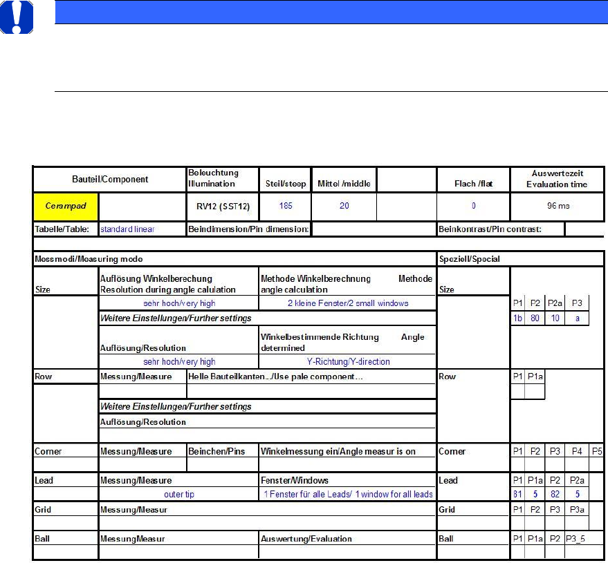
7.3 Vision parameter settings for component shapes (GF)
All settings for the Vision parameters for the various component shapes on the different ana-
logue cameras are shown in tabular format below.
These values form a database. However, the illumination values in particular also depend on the
individual camera.
NOTICE
With older machines in particular, it is generally recommended that an FCCS is carried out prior to a ma-
chine capability analysis in order to adjust the camera illumination to a standard value. This establishes a
basis for comparison.
7.3.1 SST12 and SST14 => RV12 head on ICOS machines (analog Vision)