3_AVS-V2_MCT-UM-internal_EN_07-2019.pdf - 第144页
ASM AVS - U SER M ANUAL P AGE 144 OF 182 5.3.5.3 Component (Item) positions Aft er the r equ ired glas boa rd w as s ele cte d for the reci pe l ike desc ribe d i n 4.3 .5.1 an d t he com po nents (ite ms) were lo aded i…
ASM AVS - USER MANUAL
PAGE 143 OF 182
If you have renamed an item, click on »Save« in the group »Task« to take over the new name
into the recipe.
Afterwards you can use the items right away.
5.3.5.2.6 Characteristic of components with four times measurement
Component which are bigger than 3mm, have to be measured with four times
measurement. Therefore the task template »Quadruple Picture.sit« is available.
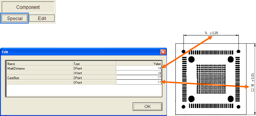
To describe the pitch of the individual measuring points and the size of the
component body, click the button »Special« in the group »Component«.
Enter the correct values for the MarkDistance (pitch) and
the CaseSize (body size).
ASM AVS - USER MANUAL
PAGE 144 OF 182
5.3.5.3 Component (Item) positions
After the required glas board was selected for the recipe like described in
4.3.5.1 and the components (items) were loaded into the recipe like in 4.3.5.2,
now the components can be distributed
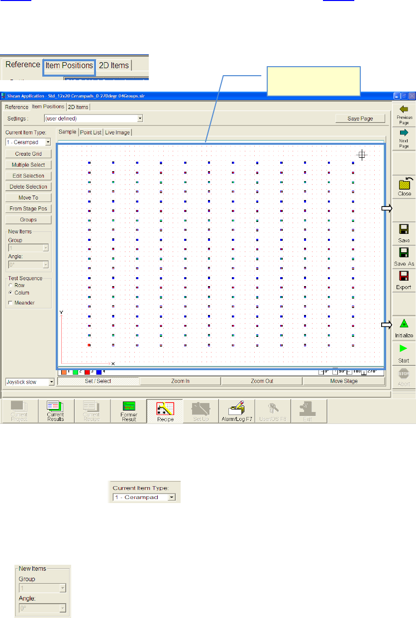
Switch to the partial view »Item Positions«.
5.3.5.3.1 Placing components on board
• Choose component.
• Activate function „Set/Select“.
• In advance you can adjust the group and angle group of the component which you want to
place now
• Click with the mouse on the position of the glas board,
where you want to place the first component
View from top side of
the board.
ASM AVS - USER MANUAL
PAGE 145 OF 182
NOTICE
If you use the automatically measuring plan creation (Create Grid) later on, it is always about the compo-
nent in the lower left corner of the later placement picture.
Generally you can place a component at any place on the board. It will be
automatically placed exactly in the center of the closest 4 points.
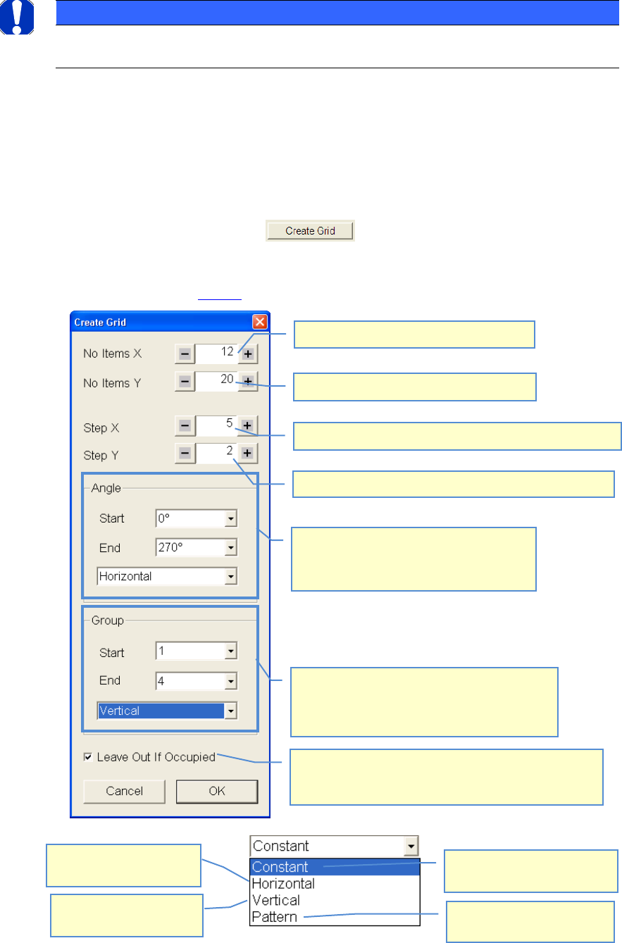
5.3.5.3.2 Fast creation of a symmetrical measuring plan
• Mark the component, by drawing a rectangle around the component with the mouse.
• Choose function „Create Grid.
• Do your settings according to your required measuring plan
• See example above 4.3.5.3:
Number of components in X-direction
Distance of components to each other in X-direction
Distance of components to each other in Y-direction
Number of components in Y-direction
The placement angle of the components can
be indicated alternatingly
90° steps are always carried out. For these 90°
steps the direction must be set.
The components can be assigned to different
groups which can then be evaluated separated. As
in the case of the angles the start and final number
as well as the course can be indicated.
The value in the start field is
taken for all components.
Group/Angle is changing in
both directions(X+Y).
Group/Angle is changing in
horizontal direction(X).
Group/Angle is changing in
vertical direction(Y)
If a second component would cover a first one due to the
settings, then the component, for which the settings were
made (marking) will not be placed but skipped.