3_AVS-V2_MCT-UM-internal_EN_07-2019.pdf - 第5页
ASM AVS - U SER M ANUAL P AGE 5 OF 182 5.3.3 »Current Recipe« ................................ ..................................................................................................... 135 5.3.4 »Former Resul…
ASM AVS - USER MANUAL
PAGE 4 OF 182
5.2.4 Change User .............................................................................................................................................. 44
5.2.5 About…. ..................................................................................................................................................... 44
5.2.6 ASM AVS Software under Start panel ....................................................................................................... 45
5.2.7 Principles of the AVS SW views ................................................................................................................. 45
5.2.8 Tables with selection check boxes ............................................................................................................ 46
5.2.9 Data Structure of the AVS Software .......................................................................................................... 46
5.2.10 Change User Password .............................................................................................................................. 47
5.2.11 Setting the Language ................................................................................................................................. 47
5.2.12 AVS Connection ......................................................................................................................................... 47
5.2.13 Placement Force Measurement ................................................................................................................ 48
5.2.14 Countries ................................................................................................................................................... 48
5.2.15 Customer Data........................................................................................................................................... 49
5.2.16 Departments ............................................................................................................................................. 51
5.2.17 Current Contacts ....................................................................................................................................... 52
5.2.18 Base Data ................................................................................................................................................... 53
5.2.19 Base Data - Capability of measuring equipment ....................................................................................... 77
5.2.20 Base Data – Import/Export ........................................................................................................................ 78
5.2.21 Base Data – Placement Force Measurement ............................................................................................ 78
5.2.22 Navigation to the SIPLACE machine .......................................................................................................... 79
5.2.23 Creating, editing, moving machines .......................................................................................................... 81
5.2.24 Projects for placement MCT ...................................................................................................................... 84
5.2.25 Projects for Printer MCT .......................................................................................................................... 104
5.3 »AVS_Scan« (measuring software) ..................................................................................... 123
5.3.1 »Current Project« and structure of »AVS_Scan« .................................................................................... 123
5.3.2 »Current Results« .................................................................................................................................... 124
ASM AVS - USER MANUAL
PAGE 5 OF 182
5.3.3 »Current Recipe« ..................................................................................................................................... 135
5.3.4 »Former Result« ...................................................................................................................................... 135
5.3.5 »Create/change recipes« ........................................................................................................................ 136
6 COMMUNICATION SERVICE NOTEBOOK ASM AVS SIPLACE .................. 151
6.1 Settings of the different network adapters ........................................................................ 151
6.2 Procedure to establish a connection (with SIPLACE Pro) ................................................... 152
6.3 Folder/Data structure of Siplace Pro .................................................................................. 153
6.3.1 Boards...................................................................................................................................................... 153
6.3.2 Tables ...................................................................................................................................................... 153
7 ATTACHMENTS .............................................................................................. 154
7.1 Corrections of Offset values on SIPLACE machines ............................................................ 154
7.1.1 Overview of Offset correction (HOW) ..................................................................................................... 154
7.1.2 Description of the offset correction (WHERE) ......................................................................................... 155
7.2 Corrections of Offset values on DEK printers ..................................................................... 163
7.2.1 WHERE to adjust? .................................................................................................................................... 163
7.2.2 HOW to adjust ......................................................................................................................................... 164
7.3 Vision parameter settings for component shapes (GF) ...................................................... 165
7.3.1 SST12 and SST14 => RV12 head on ICOS machines (analog Vision) ....................................................... 165
7.3.2 SST13 and SST14 => RV6 Kopf on ICOS machines (analog Vision) .......................................................... 167
7.3.3 SST22 and SST20 => TWIN head on ICOS machines (analog Vision) ...................................................... 168
7.3.4 SST7 and SST10 => IC-Head on ICOS machines (analog Vision) .............................................................. 170
7.4 Notes on the statistics and on the interpretation of the results ........................................ 172
7.4.1 Statistics .................................................................................................................................................. 172
7.4.2 Notes on evaluating the Single Value chart: ........................................................................................... 177
7.5 How to measure glueing machine ...................................................................................... 180
ASM AVS - USER MANUAL
PAGE 6 OF 182
1 Preface
The product ASM AVS can be used locally at the customer's premises to perform machine capa-
bility analyses (MCT) of SMD placement machines.
Machine capability tests document the ability of a production facility (fitting machine), to be able
to fulfil a predefined processing task (fit at the debit position), durably and for certain.
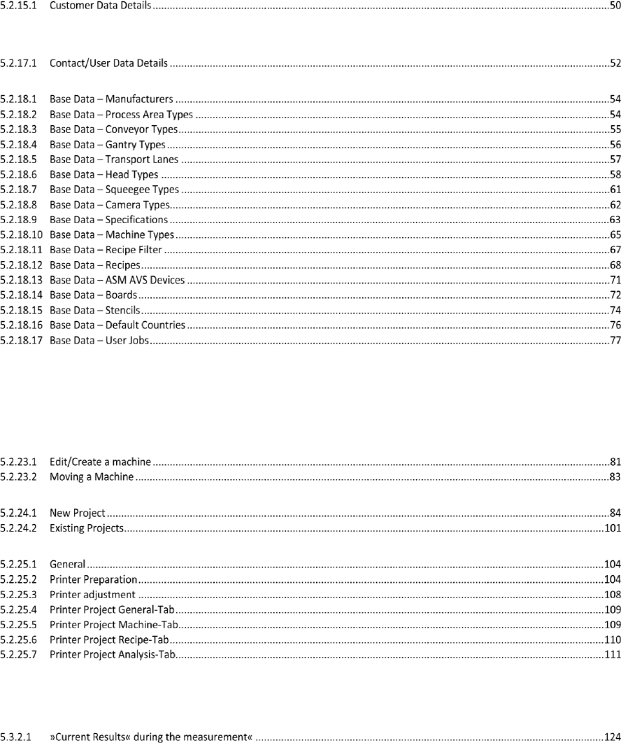
1.1 Description of the measuring method
The employed method is a so-called relative measurement.
In this method, the position of the placed components is measured relative to a structure (grid of
dots with circular fiducials) applied to the employed glass board.
In the case of chip components such as ceramic pads, simple capture using the camera is suffi-
cient to determine the component offset.
In the case of glass modules (QFP or BGA structure), the position is measured relative to the
structure of the board at the 4 fiducials present in the corners of the component. The software
then calculates the center of the component on the basis of the position of the four corner
points.
1.2 Background
The service provided with ASM AVS includes a machine capability analysis of the customer's
placement machine together with the correction of any placement offset, with the result that
customers can be issued with a certificate of the precision (machine capability) of their place-
ment machines when the operation is complete.
1.3 History OnSite MCT
1. Fine Calibration to measure accuracy on machines with analogue Vision System.
2. CmController (4 worldwide) from CeTaQ: For onsite MCT with an external device.
3. ACT, to measure accuracy on machines with digital Vision System
4. Siscan AC (11 worldwide) in-house developement Siplace Service under Siemens AG:
For OnSite MCT with an external device.
5. After leaving Siemens and the sell out of Siscan technology:
Renaming of the system to ASM AVS.
6. ASM AVS 2.0: New design, new Software, to measure screen printers and placement equip-
ment from foreign manufacturers.
Chip components
(Ceramic pads)
Glass components