3_AVS-V2_MCT-UM-internal_EN_07-2019.pdf - 第89页
ASM AVS - U SER M ANUAL P AGE 89 OF 182 (5) Reci pe L ayout : In thi s are a, the layo ut of the rec ipe (m eas ureme nt plan) is alw ays disp layed , whi ch y o u have ma rke d in t he tabl e on the top left . If you do…
ASM AVS - USER MANUAL
PAGE 88 OF 182
(3) Select Glassplate:
You have to choose a glass board that you want to use in the project.
This is, to close the loop regarding calibration data.
Each glass board must have a valid calibration certificate, as well as the AVS device.
In the drop down list you will only see the boards that are defined (connected) to the de-
vice you are working on.
It is also possible to choose 2 glass plates if 2 plates were used in the project.
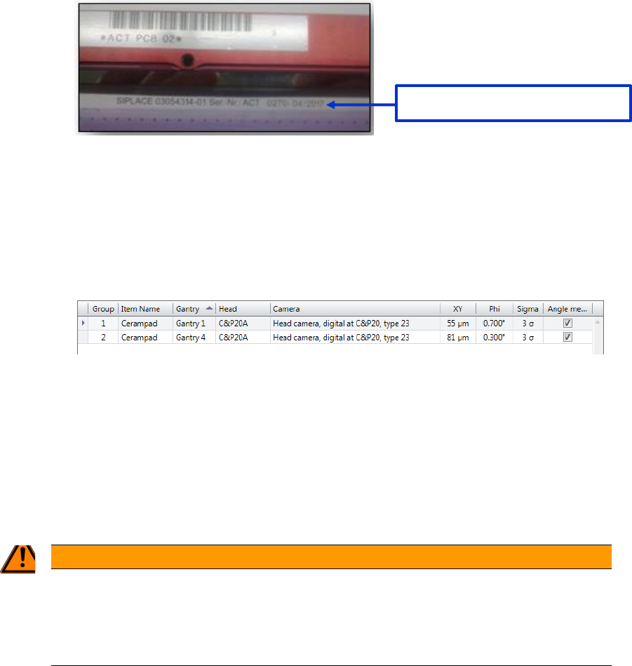
(4) Item Configuration:
Once you have selected a recipe for the project, you must assign the items, gantries,
groups, ….
Check if the Item name (link to SIPLACE Pro) is linked to the correct group and specifica-
tion values.
If this is not the case, you can change the group number (1
st
column).
- Assign the “Group” number to the corresponding Gantry.
If you Click onto a Group number, you can change the value to the required group,
via the drop-down list.
- Select the Checkbox in the “Angle” column, if you want to measure the angle on the
corresponding head.
In this view you can also change the Specification values, if you like to use different specifica-
tions in the project.
WARNING
2T! Wrong interpretation possible !
When the placement program is scheduled via Siplace Pro or the Linux line computer, you must always
make sure that the above assignment of items and groups to the relevant placement heads corresponds to
the reality!
[Serial-No.] – [production date]
ASM AVS - USER MANUAL
PAGE 89 OF 182
(5) Recipe Layout:
In this area, the layout of the recipe (measurement plan) is always displayed, which you
have marked in the table on the top left.
If you double-click on this layout, the image is displayed in a new window, which you can
then enlarge across the entire screen.
(6) Standard values:
If you have changed the specification limits for the individual groups in area (4), you can
return to the standard specification for the combination (machine/head/camera), stored
in the database, via the "Defaults" button.
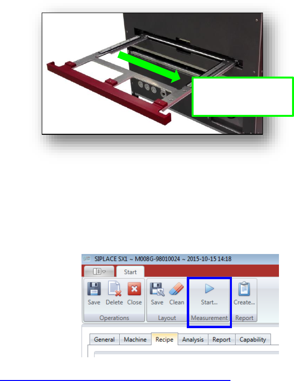
5.2.24.1.4 Starting measurement
You have inserted a populated glass plate in the drawer of the AVS and pushed it into the de-
vice as far as it will go.
AVS insertion tray for ACT glass plate
When you have done all the settings in the Tabs “General”, “Machine” and “Recipe”, you can
directly click the “Start” Button in the Menu.
The Software switches to the measuring software AVS_Scan and a measurement starts direct-
ly.
See 4.3.2.1 »Current Results« during the measurement«
Insertion direction:
Arrows on plate must
point to the right.

ASM AVS - USER MANUAL
PAGE 90 OF 182
5.2.24.1.5 Project – Analysis (placement machine)
Once the measurement in the AVS_Scan Software has finished, the software switches back to
the ASM AVS software, onto the “Analysis view”.
The “Analysis view” has 4 parts.
(1) List of measurements in the project.
In this view, the highlighting of a line (measurement) does not mean anything.
To see the measurement details, you need to activate the measurement via the check-
box!
You can select more than one measurement for the analysis.
(2) Filter for measurement data:
On top of the different tabs for analysis, you have one line (if necessary 2 lines) with
drop-down lists (and in some cases check boxes) to filter the results for all the tabs bel-
low!
(3) Result Area:
In this area, all calculations and drawn graphs are displayed, corresponding to the filter
setting above (area 2).
(4) Collecting Report Views:
Each view of area (3) can be add to the report, including a comment.
Just add the comment in the editor field and press the button .