3_AVS-V2_MCT-UM-internal_EN_07-2019.pdf - 第152页
ASM AVS - U SER M ANUAL P AGE 152 OF 182 6.2 Pr oced ure to est abli sh a con ne ctio n (wit h S IPLA CE Pro ) • D isc onnec t the line i n the GUI of the cus tomer s Si plac e P ro com pute r in t he Li ne contr ol G UI…
ASM AVS - USER MANUAL
PAGE 151 OF 182
6 Communication Service Notebook ASM AVS SIPLACE
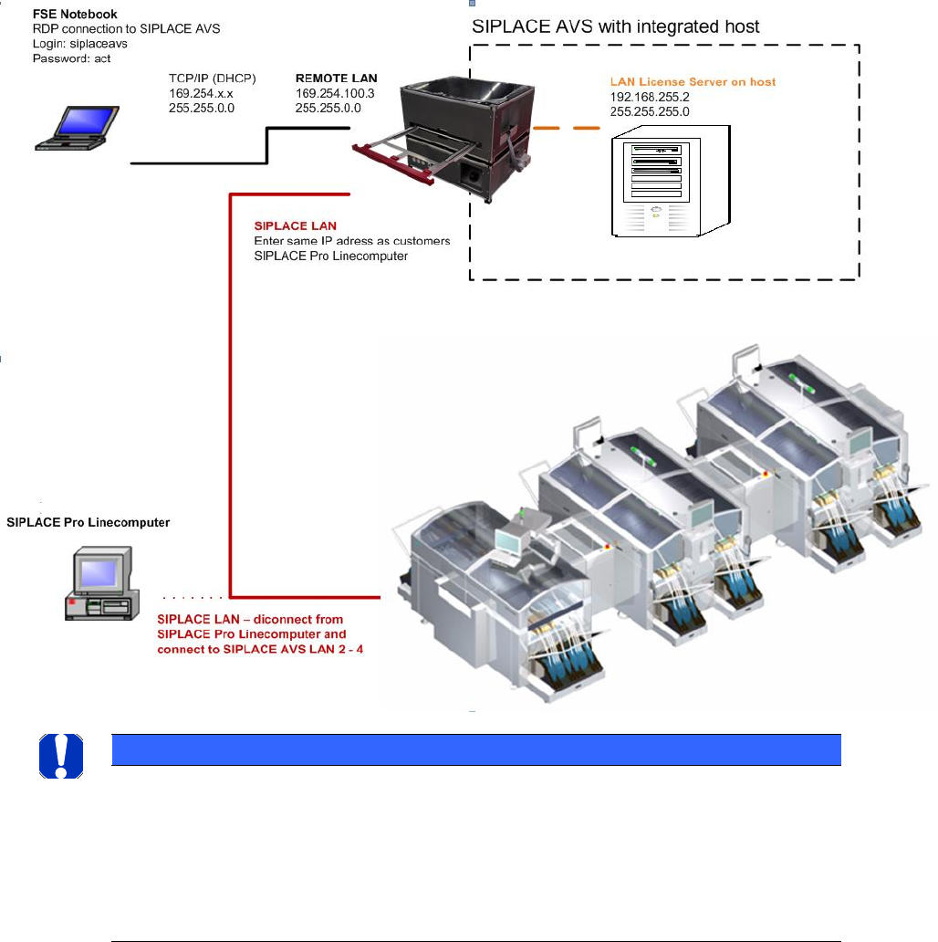
The computer of the ASM AVS device has 2 LAN ports.
One LAN Connection is named REMOTE_LAN and it is led out on the front side.
The 2
nd
LAN Connector is named SIPLACE_LAN and it is led out on the back side.
6.1 Settings of the different network adapters
To ensure error-free operation of all systems, the network adapters of the computer must have
different settings.
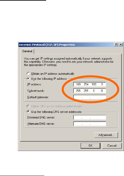
REMOTE_LAN:
The connecter named as REMOTE_LAN is allways set to a fixed network adress.
The address is always 169.254.100.x, with x for the device number (written on the top of the
LAN connector).
SIPLACE_LAN:
To be able to connect the SIPLACE line, the connector named SIPLACE_LAN must be set to a cor-
responding address on every line.
Enter the same address to this connector as the SIPLACE Pro computer from the customer has.
Disconnect the LAN cable from the customers SIPLACE Pro computer, which connects the
SIPLACE Pro computer to the stations in the line.
Connect this cable on your SIPLACE_LAN connector on the backside of the AVS.
ASM AVS - USER MANUAL
PAGE 152 OF 182
6.2 Procedure to establish a connection (with SIPLACE Pro)
• Disconnect the line in the GUI of the customers Siplace Pro computer in the Line control GUI!
• Move the ASM AVS Device close to the customer’s line computer (Siplace Pro).
Read out the IP- address of the line computer (Siplace Pro) (ipconfig).
• Give exactly the same address to the network adapter SIPLACE_LAN.
• Now you have to disconnect the LAN cable on the customers Siplace Pro computer and con-
nect it to the LAN plug on the backside of the ASM AVS.
• To verify the connection, try a ping to the IP address of one of the Siplace stations.
NOTICE
Import of the Setup from production
Basically, before you start to create stations, lines and setups, you should export the setup of the last
scheduled job at the customer Siplace Pro line computer. After the import of the data in a folder “Custom-
er Data”, you don`t have to take care about the configurations (nozzle changer, headtypes,IP-aress…) of all
machines in the line anymore. You can directly create a recipe with the prepared PCB’s and tables and
schedule to the line.
ASM AVS - USER MANUAL
PAGE 153 OF 182
6.3 Folder/Data structure of Siplace Pro
Following description should help, to get more confident with the data structure of Siplace Pro.
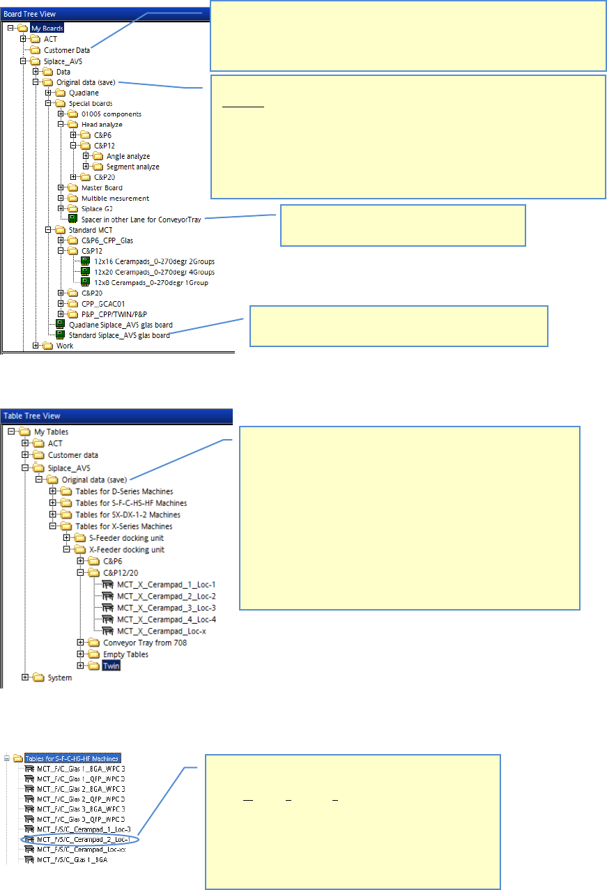
6.3.1 Boards
6.3.2 Tables
6.3.2.1 Table name convention
Folder „Customer data”: Should be used for import data which can be deleted
after you have finished your work on customer side.
E.g you can import the last scheduled job as XML-file, to get the nozzle changer
and machine configuration instead of doing this manually.
Folder »ASM AVS – Original data (save)«: All data which is stored in this folder
must not be changed.
You find all boards separated in “Special boards” and “Standard MCT”.
Under “Special boards” you will find all boards which are necessary for analyse in
case you have problems with individual segments or angles.
Under Standard MCT you find all boards separated by head types.
If you are not sure which board is the right one to choose, see also the comment
of each board.
Standard ASM AVS glass board: Template for AVS PCB’s.
There is just the new placement list to be added.
All the tables are sorted by three machine series.
You can choose between D-Series, S-F-C-HS-HF-Series and X-Series
machines. These tables can be set up via drag and drop to create a
new setup. Therefore you can create setups very fast.
On D-, X-(S-Table) and HF-series you have to take care that the tray
holder is set up on track 37 and not like scheduled from Siplace Pro ,
track 7. There are two reasons for; first one is that the tray holder
does not exist in the software of Siplace Pro, the second is because of
the reduced travel range of these machine types.
The tray holder on X- tables has to be set up on track 22
On all other machines you can setup the tray holder like in Siplace Pro
described.
The name of the table is built up in following Stepps:
MCT: Machine Capability Test
F/S/C: This table can be set up on following Machines
F: F4, F5, and F5HM
S: S20, S23HM, S25HM, and S27HM
C: CS, CF
Cerampad_1: Component set up on table
Loc-3: Location or feeder type(MTC/WPC)
»Spacer….«: Empty board as a place holder for
the Tray, with Tray in Conveyor.