3_AVS-V2_MCT-UM-internal_EN_07-2019.pdf - 第162页
ASM AVS - U SER M ANUAL P AGE 162 OF 182 Met hod 2: T he me asur ed o ffse t i s going to be c orr ect with the help of a B atch -Fi le. Wit h thi s Bat ch, t he m app ing data o f t he m achi ne a re goin g to b e corre…
ASM AVS - USER MANUAL
PAGE 161 OF 182
7.1.2.6 Platform 0 -> SPLACE S15, F3
On machines from the generation S15, F3, two possibilities are existing, to correct the meas-
ured offset.
Method 1: In the „real.ma“-file, the offset is going to be corrected on the camera, resp.
at the zero point correction of the axis. The disadvantage of this method is,
that the offset will be automatically overwritten by the next calibration in
Sitest.
The correct sequence of the entries must also be observed with this method.
Gantry 2 must be changed first. The board camera offset must be corrected for this gantry
and for the RV head on F3 machines.
Values are entered in µm, which means that no conversion is required before entry.
For gantry 1 (S15 only), the offset correction is entered under the zero point correction for
the relevant axis in the file Real.ma.
Because this value is entered in digits rather than µm, the measured value must be converted
to digits beforehand by dividing it by 2.5.
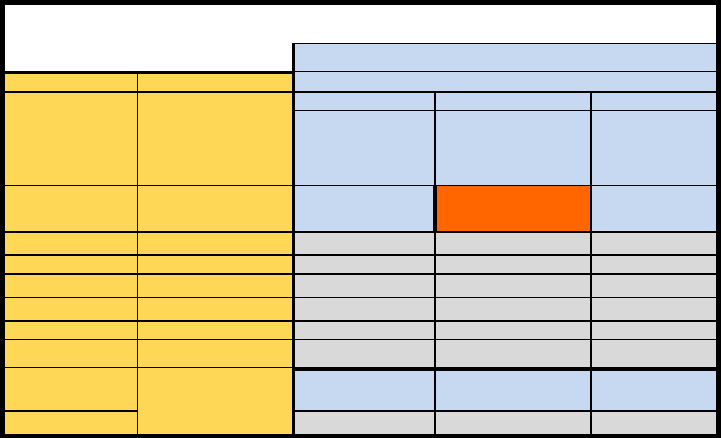
S15 / F3
Real.ma
Methode 1
SW-Version (alle)
Global
machine type
head
X / Y Portal 2
X / Y Portal 1
Winkel
Real.ma /
Kamera_Offset_
Real.ma \
Achsparameter 1 \
Portal 1 \
Nullpunktkorrektur
Real.ma /
Kamera_Offset_
Winkel
special
Korrektur in Digit !
X0 = Xgem / 2,5
S15
RV12-Kopf
X
new
= X
alt
- X
0
X
neu
= X
alt
- X
0
F3
RV12-Kopf
X
neu
= X
alt
- X
0
IC-Kopf
X
neu
= X
alt
+ X
0
O
neu
= O
alt
- O
0
G2
Kopf 3
X
neu
= X
alt
- X
0
Kopf 1 und 2
Kopf-Offset in Re-
al.ma
X
neu
= X
alt
+ X
0
ASM AVS - USER MANUAL
PAGE 162 OF 182
Method 2: The measured offset is going to be correct with the help of a Batch-File. With this
Batch, the mapping data of the machine are going to be corrected. Thereby, each
single value of the mapping grid is going to be changed.
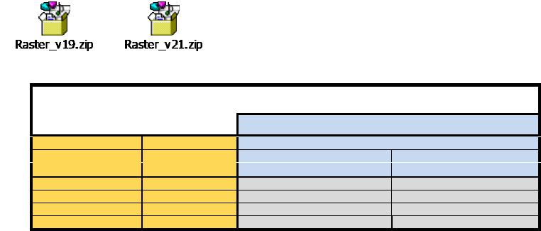
To correct the offset values in the raster-files automatically, for the MA-File Versions 19 and 21,
an application is existing.
Therefore copy the raster-files into the same folder as the application.
After you correct the offset values, using the Software application, the raster.*
files can be copied back to the station computer.
S15 / F3
Korrektur im Raster.p1, Raster.p2
Methode 2 mit Softwarehilfe
SW-Version MA-Daten ab Version 19
Global
machine type
head
X / Y
Winkel
Raster.px
Real.ma / bei Kameraoffset
S15
RV12-Kopf
Xneu = Xalt - X0
F3
RV12-Kopf
Xneu = Xalt - X0
IC-Kopf
Xneu = Xalt - X0
Oneu =Oalt - X0
ASM AVS - USER MANUAL
PAGE 163 OF 182
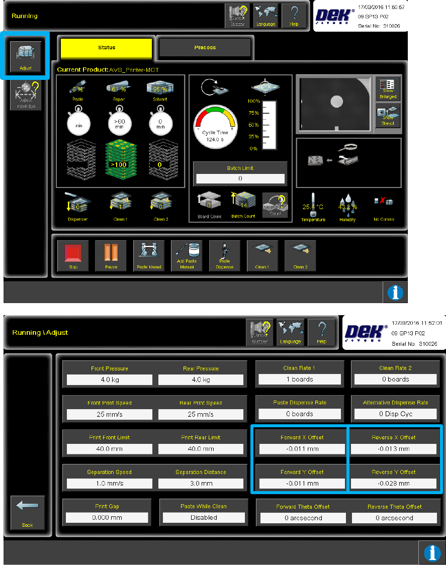
7.2 Corrections of Offset values on DEK printers
7.2.1 WHERE to adjust?
After the first plate was measured in the AVS, the captured offset values for X-, Y- and Theta,
each for both directions (back to front, front to back) can be obtained and be registered in the
printer from there.
Push the button "ADJUST" in the "Running" view, to go to the view "Running \ Adjust".