3_AVS-V2_MCT-UM-internal_EN_07-2019.pdf - 第15页
ASM AVS - U SER M ANUAL P AGE 15 OF 182 0306 3445 -01 "GC AC 0 1" ref ers to co mpo nent s of size 18x1 8mm . The fol low ing st ruct ures are ap plied to t he unde rsid e o f the se c ompo nents . 0306 3450 -0…
ASM AVS - USER MANUAL
PAGE 14 OF 182
2.1.3.2 Measurement components:
When considering the measurement components (or measurement dummies), it is necessary
to distinguish between the applications (machine configuration) for which a component is to
be used.
2.1.3.2.1 Cerampads 2x2mm on tape 00359505-01:
Used for machines or heads which are operated in Collect&Place mode and are primarily used
for the placement of chip components.
Ceramic pads are supplied under item number 00359505-01 in reels of 5000.
2.1.3.2.2 Standard SMD chip components (0201, 0402,…..):
For machines or heads that are operated in Collect&Place mode.
It is also possible to use conventional SMD chip components instead of ceramic pads. Howev-
er, these are of questionable value for MCT purposes since they are usually of worse quality
(tolerance of edge widths and lengths etc.).
CAUTION
2TDanger of wrong interpretation of the measured results!
These components should not be used until the underlying machine capability has been
demonstrated using the preferred MCT components.
2.1.3.2.3 Glass components CC02-005:
SIPLACE machines with an analog vision system possessed a fine calibration option. Glass
components (CC02-005) and other items were supplied for this fine calibration. These can al-
so be used for MCA’s for C&P 6-segment heads, resp. at all P&P heads, as an alternative.
00343702-01 glass components RV-K.6/12/IC-K.(CC02-005) with tray.
This demands the use of a tray holder, item No. 00116430-01.
2.1.3.2.4 Glass components GC AC 01, GC AC 02 und GC AC 03:
The following applies to all 3 components:
• The QFP or BGA structure is optically centered using the placement unit's component
camera.
• The solder bumps help maintain the required distance so that the glass components are
not placed across the entire area of the adhesive film.
• ASM AVS optically centers the measurement fiducials through the 0.2 mm thick glass layer
in the component pocket holes and thus calculates the position of the components relative
to the position of the fiducial on the board.
2.1.3.2.5 Overview of components:
Head
Component (standard)
component (alternative)
CP-12, CP-20, CPP (12) heads
Cerampads
GC AC 01 (BGA_DCA); SMD Chips
6er
GC AC 01 (QFP)
CC002-005
IC-Head, Twin-Head, P&P-Modul, CPP (1)
GC AC 02 (QFP) (BGA at FC-Cam.)
GC AC 01 (QFP); CC002-005
4times measurement on Twin, IC Head and
P&P-Modul
GC AC 03
ASM AVS - USER MANUAL
PAGE 15 OF 182
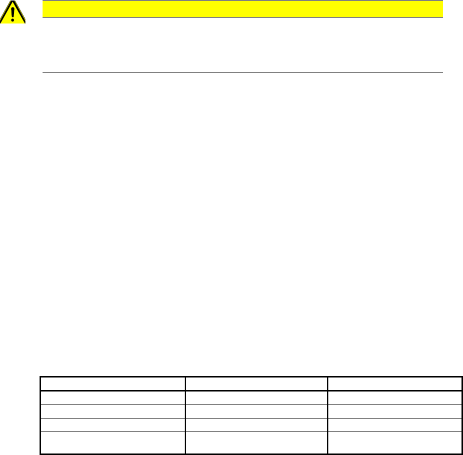
03063445-01 "GC AC 01" refers to components of size 18x18mm.
The following structures are applied to the underside of these components.
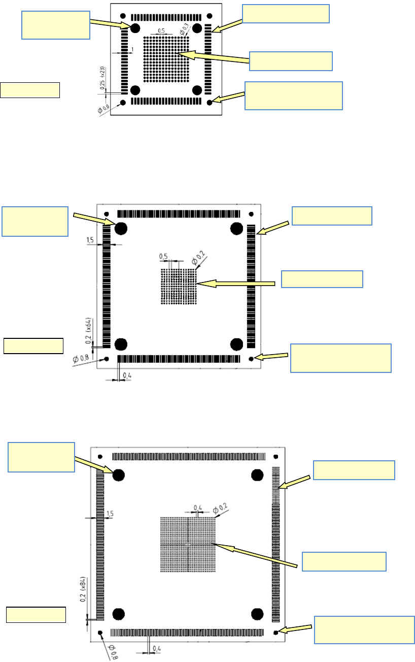
03063450-01 "GC AC 02" refers to glass components of size 32x32mm.
The following structures are applied to the underside of these components.
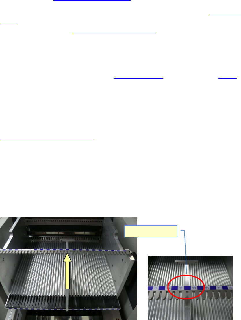
03063453-01 "GC AC 03" refers to glass components of size 42x42mm.
The following structures are applied to the underside of these components.
GC AC 01
QFP92-Structure
BGA225-Structure
Measurement fiducials
for SIIPLACE AVS
Solder bumps
(Leads)
QFP256-Structure
BGA225-Structure
Measurement fiducials
for ASM AVS
Solder bumps
(Leads)
GC AC 02
QFP336-Structure
BGA900-Structure
Measurement fiducials
for ASM AVS
Solder bumps
(Leads)
GC AC 03
ASM AVS - USER MANUAL
PAGE 16 OF 182
2.1.3.3 Trays for glass components:
There are two Trays with glass components in the standard accessories box.
• 03063444-01 Complete tray with 60 GC-AC-01
• 03063449-01 Complete tray with 40 GC-AC-02
For spare parts, see documentation Checklist AVS.
The form of the tray allows you, either to place the tray onto a tray holder (see 2.1.3.5 Tray
holder), or to place it into the conveyor of the SIPLACE machine like a PCB. Therefore see ad-
ditional instructions under 2.1.3.6 Tray in the PCB conveyor.
2.1.3.4 Adapters for tray on the WPC / MTC
To use a Tray on a WPC/MTC an additional adapter is needed to be able to align the tray on
the tray carrier plate. These adapters are always with the Tray and have to be removed from
it, if using the tray on another tray carrier (2.1.3.5 Tray holder) or in the conveyor (2.1.3.6).
• 03069672-01 „Adapter long ACT Tray on WPW/MTC“
• 03069673-01 „Adapter short ACT Tray on WPW/MTC“
2.1.3.5 Tray holder
There are two tray carriers in the standard accessories box. These are to place the Trays (see
2.1.3.3 Trays for glass components:) on the tables of the Siplace.
• 03059291-01 „Tray holder X“
• 03059289-01 „Tray holder S“
2.1.3.5.1 03059291-01 „Tray holder X“
This tray holder is to use in X-Machines with X-tables.
The design of the tray carrier follows the concept of an X-Feeder.
and has to be set up in the same way like standard X-Feeders.
Place on Track 22