3_AVS-V2_MCT-UM-internal_EN_07-2019.pdf - 第150页
ASM AVS - U SER M ANUAL P AGE 150 OF 182 5.3.5.5 Export of the Recipe Data (CAD Data) Aft er the glas plate was choo sen , l ike i n 4 .3.5 .1 , the com pone nts (Item s) are loade d int o t he re cipe like i n 4 .3 .5.2…
ASM AVS - USER MANUAL
PAGE 149 OF 182
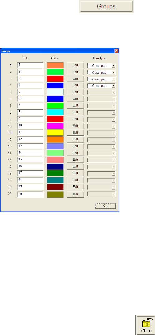
5.3.5.3.9 Assign group colors
• Choose function »Groups«.
• You can assign any color you like to each group, by using the following dialog.
Basically all 20 groups are visible in the dialog window but only the used groups have as-
signed a component.
5.3.5.4 Storage of a Recipe (measuring plan)
Once you have created or changed a recipe, you can save the recipe.
Save all the recipes into the folder: »C:\ ASM AVS Data\Recipe«.
In this folder you have to create a sub folder with the desired name of your recipe.
To find the recipes again, it is helpful to use names that are showing information about the
content of the recipe, like »20x12_Cerampads_4 Groups_0-270degr«.
Use the same name for the new sub folder as well as for the file name.
Exit the Siscan Application with the button »Close«!
You come back to the » ASM AVS Software«, automatically.
There you have to edit some parameters to add the recipe into the Database.
ASM AVS - USER MANUAL
PAGE 150 OF 182
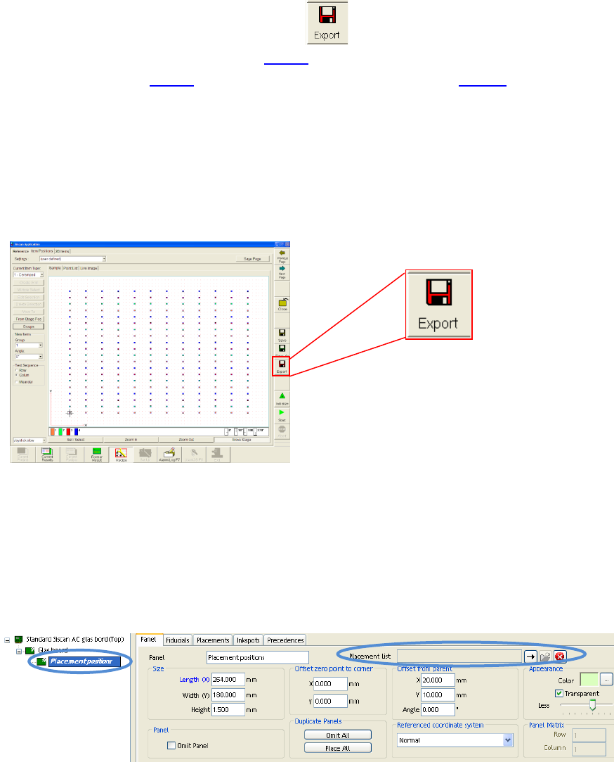
5.3.5.5 Export of the Recipe Data (CAD Data)
After the glasplate was choosen, like in 4.3.5.1, the components (Items) are loaded
into the recipe like in 4.3.5.2 and components place in a layout like in 4.3.5.3, the
data can be exported, to import it as placement positions into a SIPLACE Pro PCB de-
scription.
A Textfile is created which you can import into Siplace Pro via the
»ASCII Centroid Import Wizzard«.
You find this function in the »Recipe Editior«.
Finally this placement list has to be inserted in the template board
»Standard ASM AVS glass board« into the last sub panel called »Placement posi-
tions«.
See picture below
ASM AVS - USER MANUAL
PAGE 151 OF 182
6 Communication Service Notebook ASM AVS SIPLACE
The computer of the ASM AVS device has 2 LAN ports.
One LAN Connection is named REMOTE_LAN and it is led out on the front side.
The 2
nd
LAN Connector is named SIPLACE_LAN and it is led out on the back side.
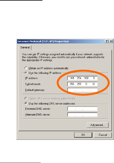
6.1 Settings of the different network adapters
To ensure error-free operation of all systems, the network adapters of the computer must have
different settings.
REMOTE_LAN:
The connecter named as REMOTE_LAN is allways set to a fixed network adress.
The address is always 169.254.100.x, with x for the device number (written on the top of the
LAN connector).
SIPLACE_LAN:
To be able to connect the SIPLACE line, the connector named SIPLACE_LAN must be set to a cor-
responding address on every line.
Enter the same address to this connector as the SIPLACE Pro computer from the customer has.
Disconnect the LAN cable from the customers SIPLACE Pro computer, which connects the
SIPLACE Pro computer to the stations in the line.
Connect this cable on your SIPLACE_LAN connector on the backside of the AVS.