3_AVS-V2_MCT-UM-internal_EN_07-2019.pdf - 第146页
ASM AVS - U SER M ANUAL P AGE 146 OF 182 5.3.5.3.3 Mu ltiple Select • M ark t he compo nent , by dr awi ng a rect ang le aro und the com pone nt wi th the rig ht mo use but ton. • C hoo se f unct ion »Mu lti ple S elect …
ASM AVS - USER MANUAL
PAGE 145 OF 182
NOTICE
If you use the automatically measuring plan creation (Create Grid) later on, it is always about the compo-
nent in the lower left corner of the later placement picture.
Generally you can place a component at any place on the board. It will be
automatically placed exactly in the center of the closest 4 points.
5.3.5.3.2 Fast creation of a symmetrical measuring plan
• Mark the component, by drawing a rectangle around the component with the mouse.
• Choose function „Create Grid.
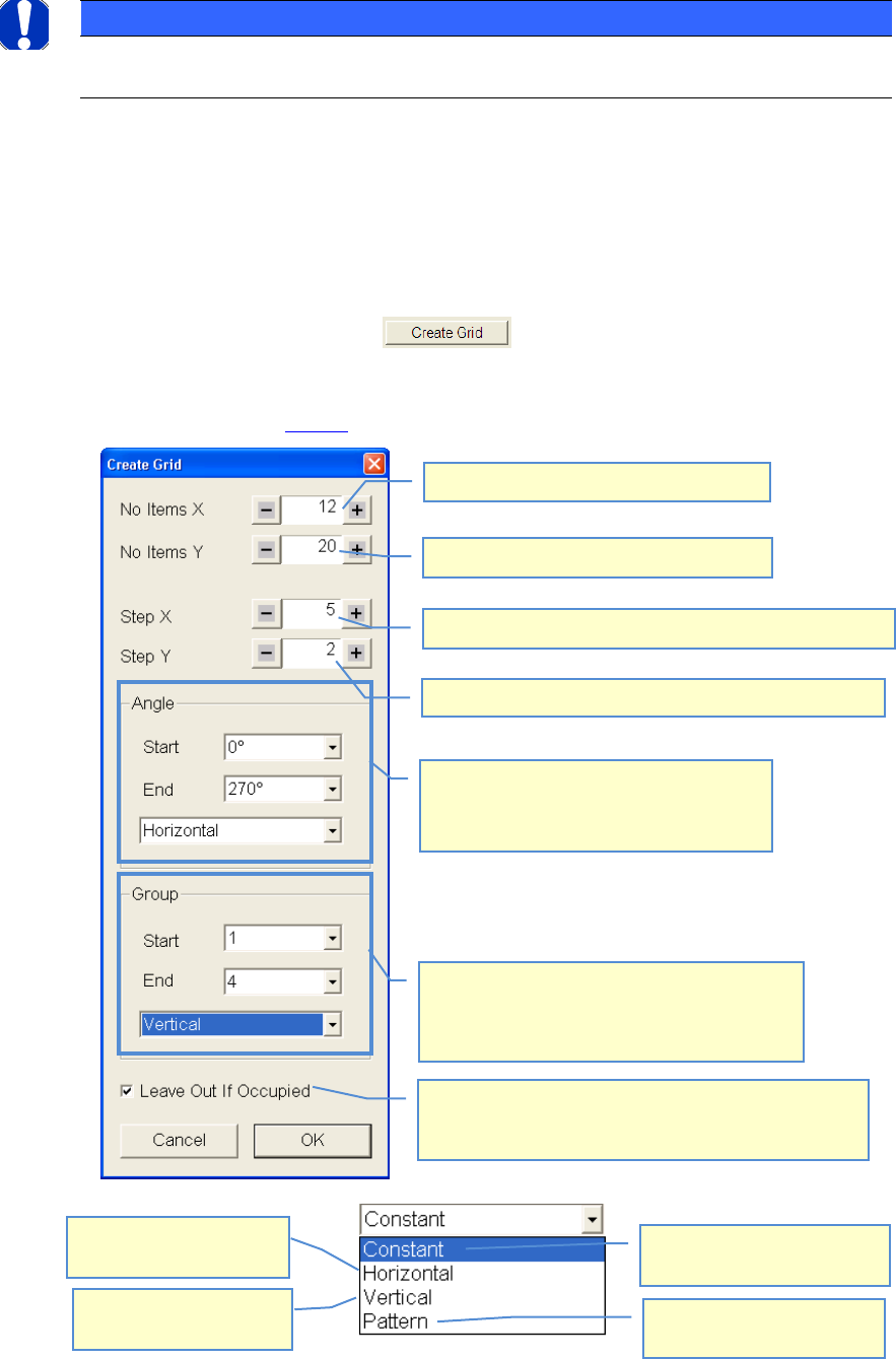
• Do your settings according to your required measuring plan
• See example above 4.3.5.3:
Number of components in X-direction
Distance of components to each other in X-direction
Distance of components to each other in Y-direction
Number of components in Y-direction
The placement angle of the components can
be indicated alternatingly
90° steps are always carried out. For these 90°
steps the direction must be set.
The components can be assigned to different
groups which can then be evaluated separated. As
in the case of the angles the start and final number
as well as the course can be indicated.
The value in the start field is
taken for all components.
Group/Angle is changing in
both directions(X+Y).
Group/Angle is changing in
horizontal direction(X).
Group/Angle is changing in
vertical direction(Y)
If a second component would cover a first one due to the
settings, then the component, for which the settings were
made (marking) will not be placed but skipped.
ASM AVS - USER MANUAL
PAGE 146 OF 182
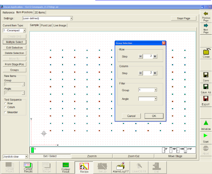
5.3.5.3.3 Multiple Select
• Mark the component, by drawing a rectangle around the component with the right mouse
button.
• Choose function »Multiple Select«.
• A window »Group Selection« will open. Here you can set the grid (Row/Colum) of which
component you want to mark within your filter settings.
• Later you can change some settings of the marked components with the
function »Edit Selection«. See 4.3.5.3.4 Move components, change grid
In this case every second component in Y- and X-direction is marked.
ASM AVS - USER MANUAL
PAGE 147 OF 182
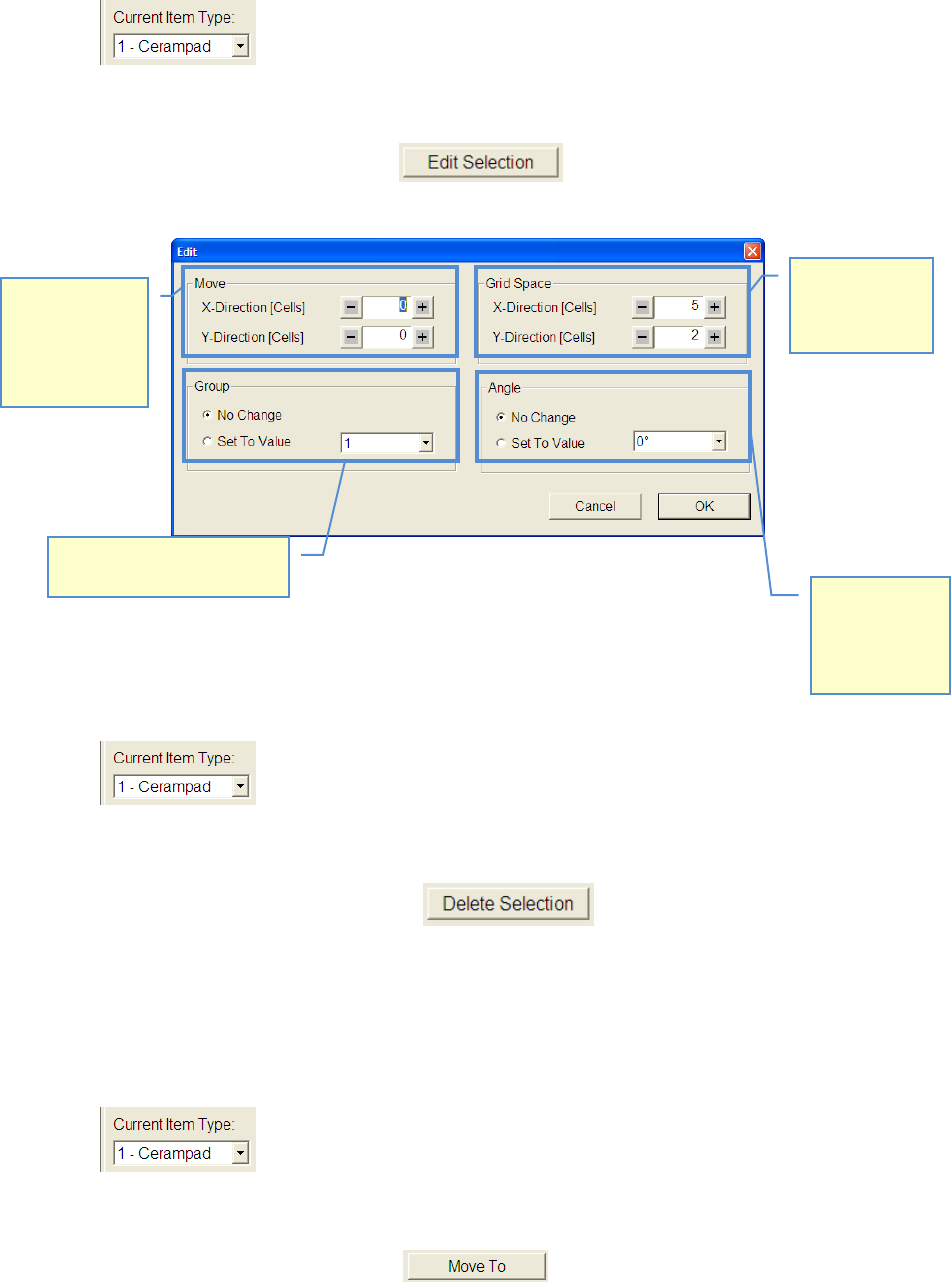
5.3.5.3.4 Move components, change grid
• Choose desired Item.
• Mark the components, you want to change by drawing a rectangle around the component
with the right mouse button
• Select function »Edit Selection«
• Modify your settings according to your desired measuring plan.
5.3.5.3.5 Delete components from recipe
• Choose component type which you want to delete.
• Mark the components, you want to delete by drawing a rectangle around the component
with the right mouse button.
• Select function »Delete Selection« , or push »Delete« button on key-
board.
5.3.5.3.6 Approach component with camera
• Select component you want to approach.
• Mark the components, you want to delete by drawing a rectangle around the component
with the right mouse button.
• Click on the button »Move To«. .
Distance of
components to
each other can
be changed
Marked compo-
nents can be
moved in X-
(horizontal) and
Y-direction
(vertical)
The angle of
marked com-
ponents can be
changed to
another value.
The group of marked compo-
nents can be changed.