4OM-1003-007.pdf - 第130页
(2) Attachment of Miniature Stroke Bearing to Head (2-1) Insert the MSB outer cylinder from under the head. Align the cylinder such that the cutout of the MSB outer cylinder faces the inside of the head. (2-2) Insert the…
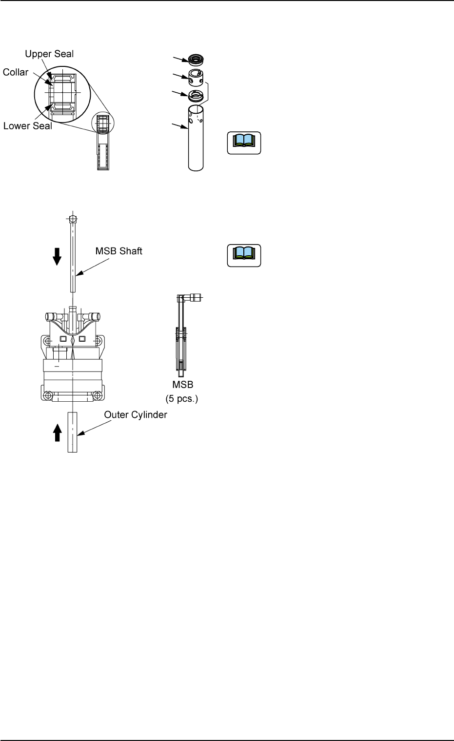
• Attachment of Miniature Stroke Bearing
(1) Attach the seals and the collar to the MSB
outer cylinder.
(1-1) Wipe the seals with a dry cloth and apply
"DAPHNE EPONEX GREASE No. 1" to
the internal side of the seals.
When the grease is not applied to the
seals, the smooth movement of the
MSB outer cylinder cannot be ex-
pected.
(1-2) Attach the lower seal, the collar, and the
upper seal to the MSB outer cylinder in
this order.
(a) When the seals are attached, do
not damage the seals by the MSB
outer cylinder.
(b) Do not make a mistake in deter-
mining the direction of the seals.
(c) After the lower seal is attached,
confirm that the lower seal is
affixed horizontally before the collar
attachment.
When the lower seal is not at-
tached horizontally, the smooth
movement of the MSB outer cylin-
der cannot be expected.
(d) When the collar is attached, con-
firm that the boss is neatly set in
the hole of the MSB outer cylinder.
0305-001 1-63
AIL01ETRP
Fig. 4A79
Fig. 4A80
1.4 Maintenance Method
Upper Seal
Collar
Lower Seal
MSB Outer
Cylinder
Note
Note
(2) Attachment of Miniature Stroke Bearing to
Head
(2-1) Insert the MSB outer cylinder from under
the head.
Align the cylinder such that the cutout
of the MSB outer cylinder faces the
inside of the head.
(2-2) Insert the MSB shaft from the top of the
head with the MSB inserting jig being
attached.
(2-3) Detach the MSB inserting jig.
If the jig is slippery, wipe it with a cloth
soaked in industrial alcohol.
(2-4) Attach the anchor plate to the MSB outer
cylinder and secure it with the screw
(M3L10).
Apply "Screw Lock (1401B)" to the screw
and tighten it with a tightening torque of 7
kgfcm.
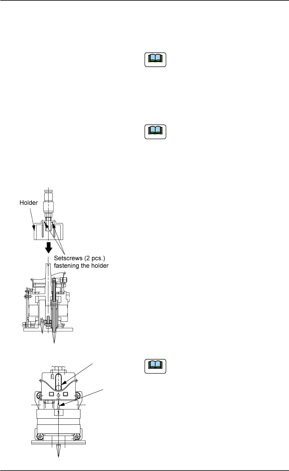
(3) Attachment of Holder to Head
(3-1) Apply "DAPHNE EPONEX GREASE No.
1" thinly to the bearing guide section of
the holder and the pin end.
(3-2) Match the holder guide with the cutout of
the head’s center shaft and insert the
holder into the top of the head.
(3-3) Push the holder into the shaft until it
stops and match the marker of the cam
unit with the center of the cam follower.
(3-4) Apply "Screw Lock (1401B)" to the set-
screws and tighten them with the 1.5 mm
bit (Standard Accessory Part: 630 116
3659) and a tightening torque of 5 kgfcm.
To avoid damaging the tapped hole,
use a hexagon wrench (TONE,
BONDUS) that fits the diagonal dimen-
sions.
Fig. 4A81
0305-001 1-64
AIL01ETRP
1.4 Maintenance Method
Cam Follower
Marker of Cam Unit
Fig. 4A81-1
Note
Note
Note
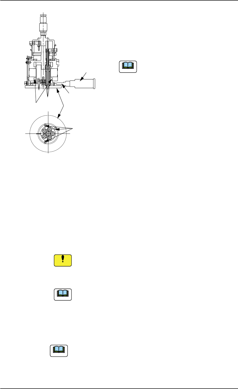
(4) Attach the diffusion plate to the head.
Tighten 3 special anti-loosening screws
(silicon-varnished ones) with a tightening
torque of 10 kgfcm, using the 2 mm bit
(standard accessory part: 630 116 3673).
Do not allow any solvent, alcohol, etc.,
to adhere to the diffusion plate. Other-
wise, the diffusion plate may crack.
(5) Apply "DAPHNE EPONEX GREASE No. 1"
thinly to the cam face of the holder.
(6) Attachment of Head Assembly to Head Assembly Holder
(6-1) Fit the pilot pin hole on the rear side of the head assembly into
the pilot pin on the holder side.
(6-2) Fasten the head assembly, using 2 screws (M4X12) for the up-
per face and 2 screws (M4X16) for the lower face.
(Tightening Torque: Approx. 44 kgfcm)
Do not make a mistake in selecting the length of screws. Oth-
erwise, the screw thread of the head will be damaged.
(6-3) Insert the hose.
Do not apply a wrench, etc., to the magnet for head origin
detection. Otherwise, the magnet will be demagnetized.
If the magnet is demagnetized, the origin may not be
detected.
(7) Perform the "Head/Nozzle" and the "Head Origin" offset teaching
operations on the attached nozzle.
Refer to "5.1 "Head/Nozzle" Tab" and "5.2 "Head Origin"
Tab" in "Section 6" of "Vol. 2: Operation (Supervisor)" for
the offset teaching operations.
• The head origin offset must be ±3 degrees or less.
• The head center offset must be ±3 mm or less.
0511-003 1-65
AIL01ETRP
1.4 Maintenance Method
Fig. 4A82
Setscrews
(3 pcs.)
Magnet for Head
Origin Detection
Diffusion Plate
2 mm Bit
Torque Screwdriver
(630 044 2786)
Note
Note
Note
Notice