4OM-1003-007.pdf - 第401页
• Checkpoints on T ape Feeder 0305-001 2-213 AIL01ETRP Fig. 4B33 Fig. 4B34 5.2 T roubleshooting on Pick-Up Errors
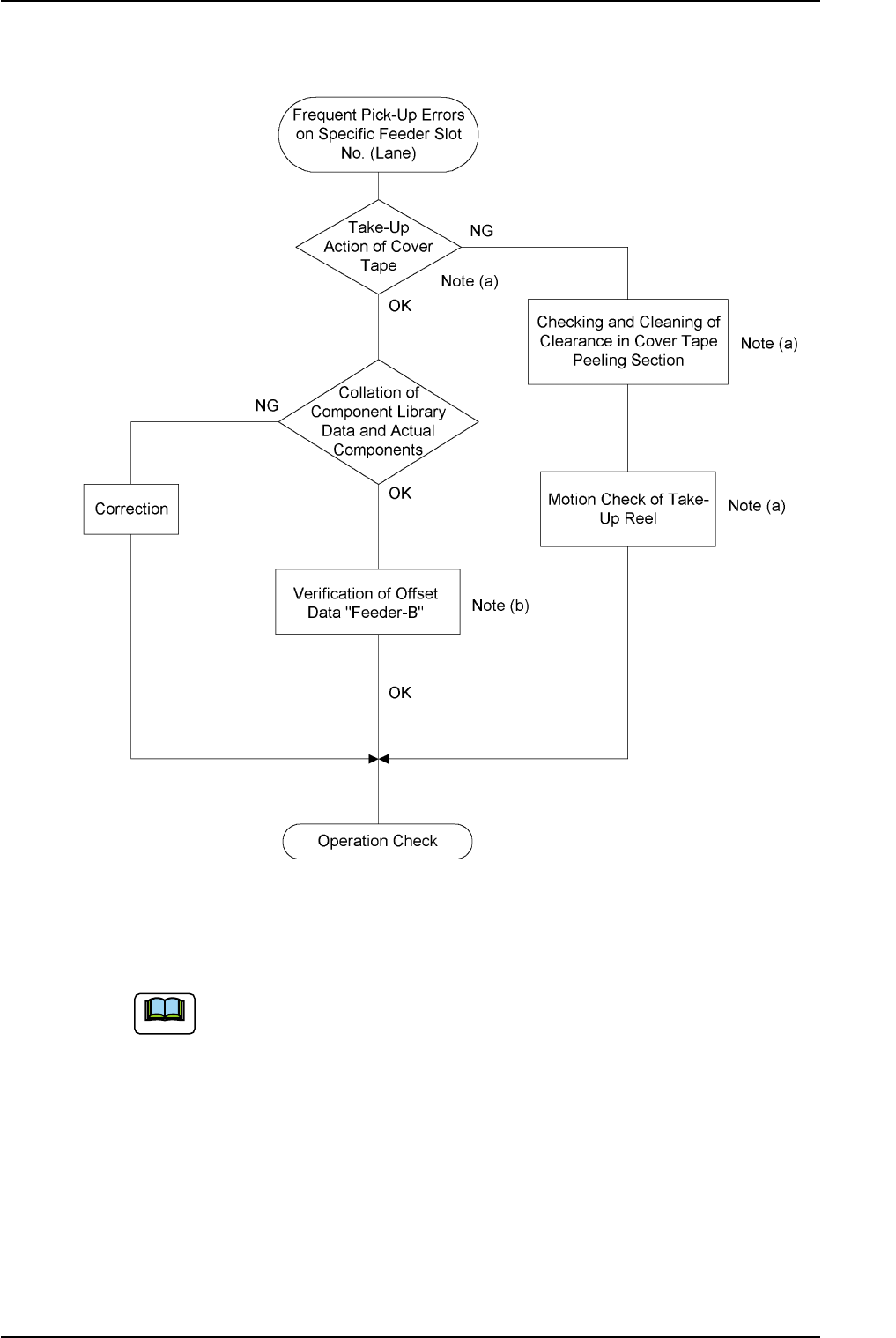
(2) Frequent Pick-Up Errors on Specific Feeder Slot No.
Fig. 4B32
(a) See Figs. 4B33 and 4B34 on the next page for the check-
points on tape feeders.
(b) When a tape feeder loaded with different components is
installed, the pick-up position must be checked and the
offset data "Feeder-B" must be cleared or modified for the
new components after program change operation because
it is prepared for the previous components.
0305-001 2-212 AIL01ETRP
5.2 Troubleshooting on Pick-Up Errors
Note
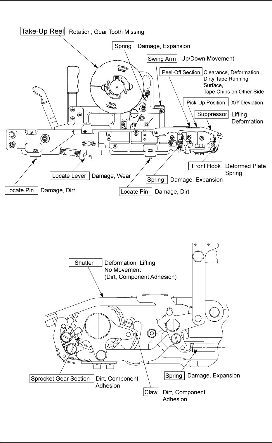
• Checkpoints on Tape Feeder
0305-001 2-213
AIL01ETRP
Fig. 4B33
Fig. 4B34
5.2 Troubleshooting on Pick-Up Errors
5.3 Troubleshooting on Placement Errors
5.3.1 Cause and Remedy of Placement Errors
(1) Positional and Angular Deviations of Component Placement
(1-1) Situational Grasp of Error Generation
Positional and angular deviations may be generated in either Process
C or D and E.
See Fig. 4B29.
By placing a component on the P.C.B. where a double-faced adhesive
tape is affixed, it can be checked and determined in which process
positional and angular deviations are generated.
When a positional deviation is generated on the double-faced tape, it
indicates that positional and angular deviations occur in Process C.
When no positional deviation is generated, it means that positional and
angular deviations occur in Process D or E.
(1-2) Positional and Angular Deviations in Process C
When a positional deviation is generated due to the movement of the
head after component recognition or a rotational deviation by place-
ment angle correction, the deviation may be caused mainly by the fol-
lowing two factors.
• Deterioration of Vacuum Suction Force
• Vibration or Shock during Nozzle (Head) Movement
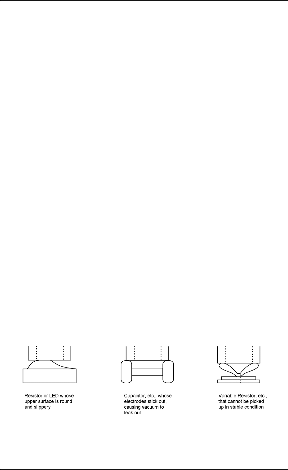
When one of the above factors exists, unstable components (compo-
nents that cannot be picked up in stable condition) such as those shown
in Fig. 4B35 are directly affected.
When a positional deviation is generated on the components (the com-
ponents of the same type that have been used in the past actual pro-
duction), check for the above-described factors.
As for vacuum suction force, check the nozzle and the vacuum line.
As for vibration during nozzle movement, check the related spots in the
range of Process C.
Fig. 4B35 Easily-Dislocated Components during Place-
ment (Example 1)
0305-001 2-214
AIL01ETRP
5.3 Troubleshooting on Placement Errors