4OM-1003-007.pdf - 第205页
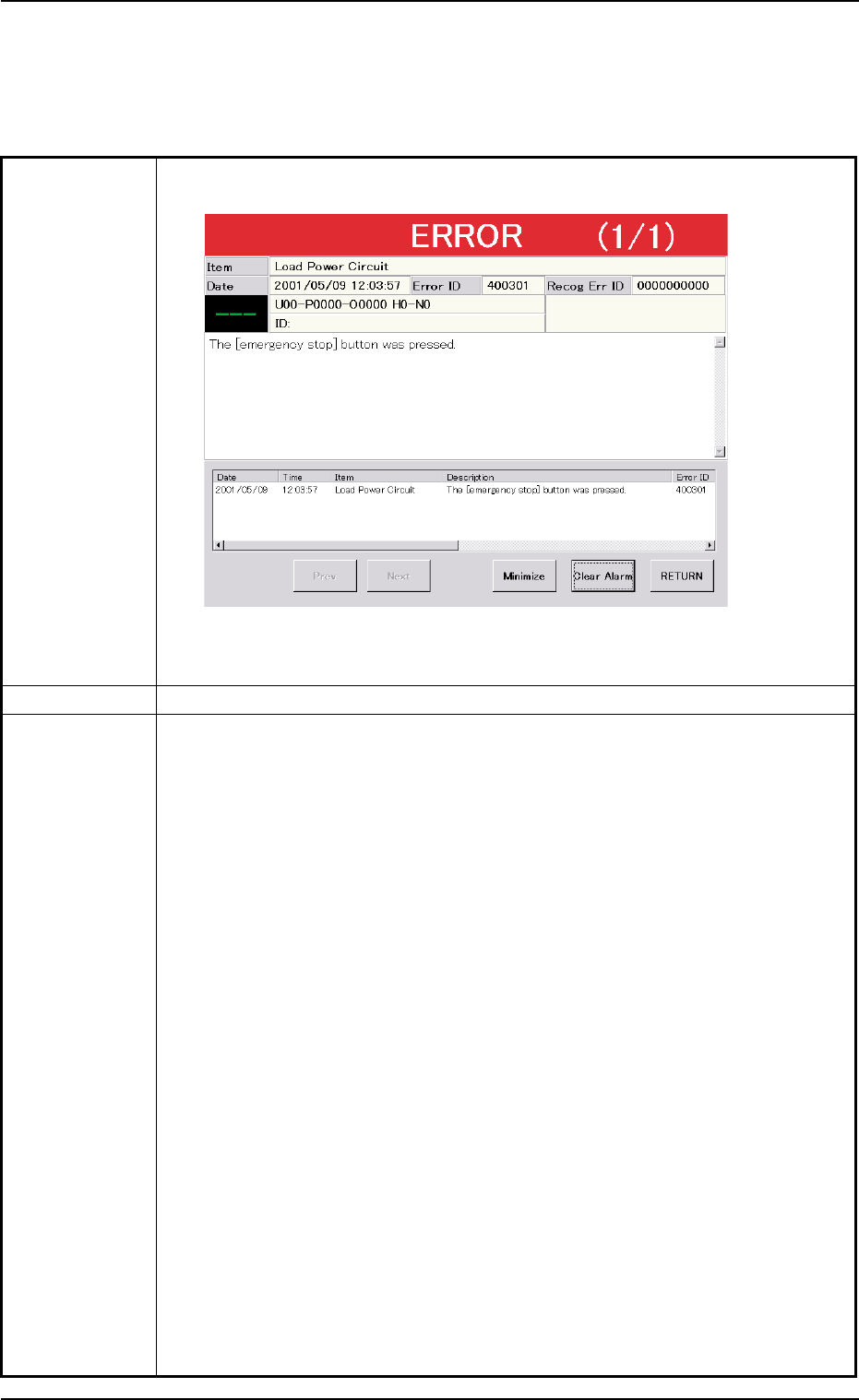
2.3 [EMERGENCY ST OP] Switch Pressed 2.3.1 During Automatic Operation T able 4B5 Symptom (1) The [POWER ON] button turns red and the following window opens. Fig. 4B7 Cause (1) An [EMERGENCY STOP] switch was pressed. Reme…

2.2 Nothing Displayed on Touch Screen
Table 4B4
Symptom Nothing is displayed on the touch screen.
Cause (Cause 1) The screen saver function is activated.
(Cause 2) Power is not supplied from the source.
Remedy (Remedy 1) Touch a part of the touch screen. The foreground activities will
occur in any running application.
(Remedy 2) Refer to "2.1 Power Operation Impossible" for details and follow
the remedial procedure.
0305-001 2-24 AIL01ETRP
2.2 Nothing Displayed on Touch Screen
2.3 [EMERGENCY STOP] Switch Pressed
2.3.1 During Automatic Operation
Table 4B5
Symptom (1) The [POWER ON] button turns red and the following window opens.
Fig. 4B7
Cause (1) An [EMERGENCY STOP] switch was pressed.
Remedy (1) Press the [RETURN] button.
(2) Check for fallen components and remove them if any.
Check the areas below the vacuum nozzles located between Stations #12
and #6.
Especially, when a component has fallen on the camera in the component
recognition section (Station #3), be sure to remove it.
(3) Check the tape feeders.
When a component to be picked up still remains in the cavity of a tape,
remove it from the cavity.
(4) Unlock the [EMERGENCY STOP] switch.
(5) Hold down the [POWER ON] button for more than 1 second to re-supply
power to the machine.
• When the LED of the [POWER ON] button turns yellowish green, it indi-
cates that power is supplied to the machine.
When the LED is kept red, re-check the cause and remove it.
(6) Press the [ALL] button (entitled "ZERO") in the "AUTO OPN." window. In 2
seconds, press the [ENABLE] button on the operation panel to zero all
devices.
(7) Check whether or not the P.C.B. in the middle of component placement is
located out of the positioning section or the components are normally placed
(not dispersed).
0305-001 2-25 AIL01ETRP
2.3 [EMERGENCY STOP] Switch Pressed
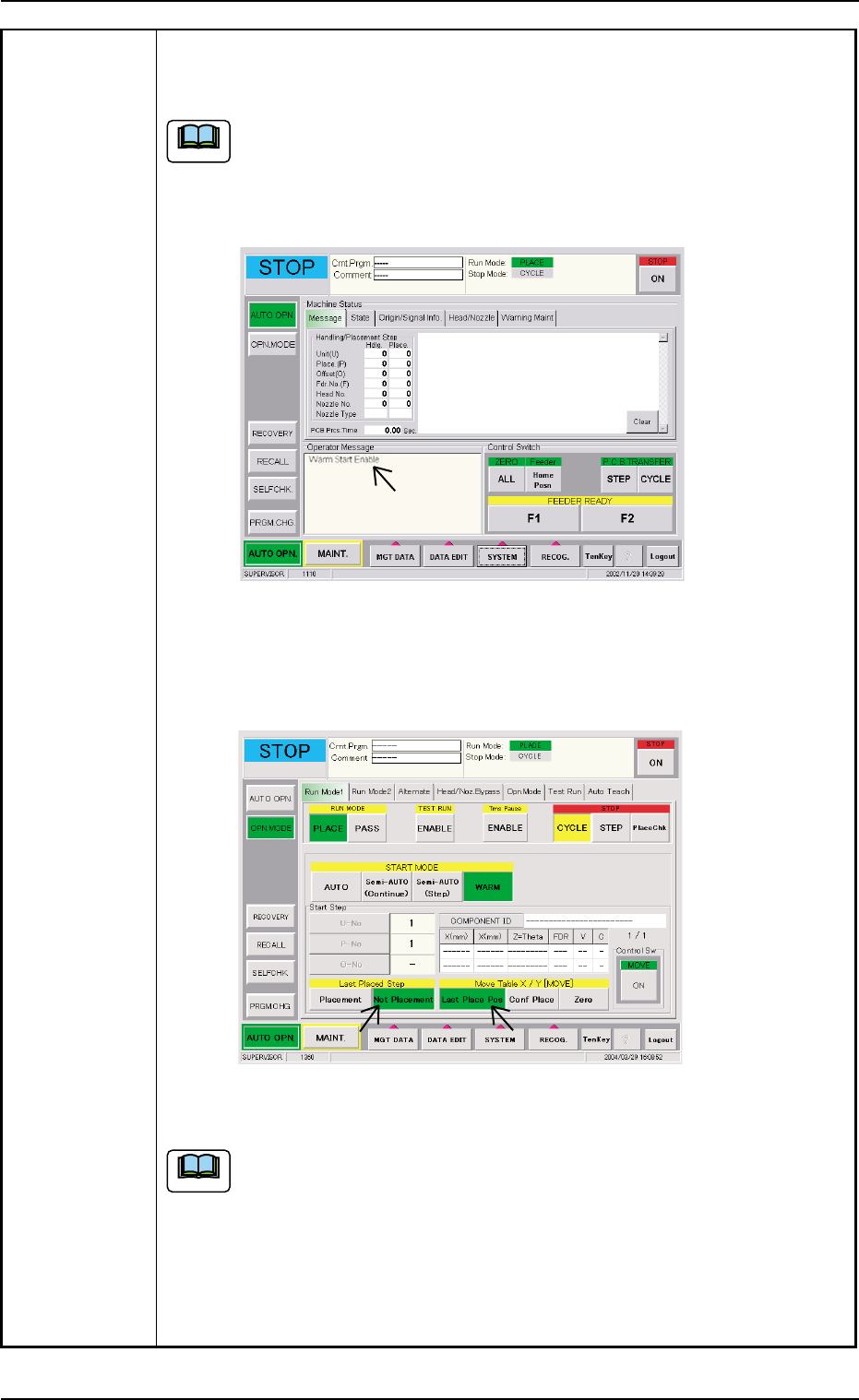
(8) When the message "Warm Start Enable" is displayed in the "Operator
Message" pane in the "AUTO OPN." window, it means that the "Warm
Start" operation is feasible.
(a) "Warm Start Enable" means that the production is interrupted in
the middle of component placement.
(b) When the operation is interrupted without any component being
placed, "Warm Start" becomes impossible.
Fig. 4B8 "AUTO OPN." Window (Submenu)
(9) Press the [OPN. MODE] button on the submenu bar. The "OPN. MODE"
window (submenu) opens.
Fig. 4B9 "OPN. MODE" Window (Warm Start Available Mode)
(a) When the "Warm Start" operation is feasible, the [WARM] button
appears in the "OPN. MODE" window (submenu).
(b) When the [WARM] button is not displayed, it means that the "Warm
Start" operation is not feasible or there was a mistake in the re-
medial procedure after an error had occurred. In this case, per-
form the semi-automatic operation (step designation) to reset the
machine to its normal condition.
2.3 [EMERGENCY STOP] Switch Pressed
0412-002 2-26 AIJ01ETRP
Note
Note