4OM-1003-007.pdf - 第296页
Error ID Item Description 430301 Head No. The head no. Detection sensor was not activated. (Cause 1) Self-Diagnostics Error Message (Remedy 1) Zero all axes and re-start the operation. When the machine cannot be set to i…

Error ID Item Description
430210 NOZZLE POSITION Component output error(Pickup error) is detected by nozzle
level was high position. ;Nozzle posture detection
430211 NOZZLE POSITION Component output error(Pickup error) is detected by nozzle
level was low position. ;Nozzle posture detection
(Cause 1) The mispicked component could not be discharged.
(Remedy 1) Check the contents of the error and re-start the operation.
Refer to "2.7 Component Backtrack Detection Function" (Section 2) in "Vol. 2"
for details.
430212 NOZZLE POSITION Component output error(Others) is detected by nozzle level
was high position. ;Nozzle posture detection
430213 NOZZLE POSITION Component output error(Others) is detected by nozzle level
was low position. ;Nozzle posture detection
(Cause 1) The error-caused component (an error other than a pickup one) could not be dis-
charged.
(Remedy 1) Check the contents of the error and re-start the operation.
Refer to "2.7 Component Backtrack Detection Function" (Section 2) in "Vol. 2"
for details.
430214 NOZZLE POSITION Upper limit of nozzle posture detection data was out of range.
430215 NOZZLE POSITION Lower limit of nozzle posture detection data was out of range.
430216 NOZZLE POSITION Nozzle posture detection was not detected full range.
(nozzle posture detection is dirty condition)
430217 NOZZLE POSITION Nozzle posture detection was Alarm.
(nozzle posture detection is dirty condition)
(Cause 1) The sensor is set in the E/NR (Light Emitted and Not Received) mode until the
zeroing operation is completed after the machine is powered.
(Remedy 1) Confirm that no dirt adheres to the sensor. Or, it may be necessary to replace
the sensor with a new one because it may be defective.
Before replacing the sensor, contact our service personnel for some advice.
0511-002 2-100-1 AIL01ETRP
3.3 Error IDs and Remedial Procedures

Error ID Item Description
430301 Head No. The head no. Detection sensor was not activated.
(Cause 1) Self-Diagnostics Error Message
(Remedy 1) Zero all axes and re-start the operation.
When the machine cannot be set to its normal condition, consult our service
personnel for the remedy.
430401 X/Y Table P.C.B. was dislodged while the X/Y table was in motion.
430402 X/Y Table P.C.B. was dislodged while the X/Y table was in motion.
(Cause 1) The P.C.B. is trapped on the X/Y table.
The P.C.B. pilot pin, the positioning lever, and the P.C.B. support pin are not lo-
cated at their regular positions.
(Remedy 1) Check how the P.C.B. pilot pin, the positioning lever, and the P.C.B. support pins
are attached.
430403 X/Y Table X/Y chute has gone up while X/Y table was in motion.
(Cause 1) Self-Diagnostics Error Message
(Remedy 1) Zero all axes and re-start the operation.
When the machine cannot be set to its normal condition, consult our service
personnel for the remedy.
0511-003 2-101 AIL01ETRP
3.3 Error IDs and Remedial Procedures
Error ID Item Description
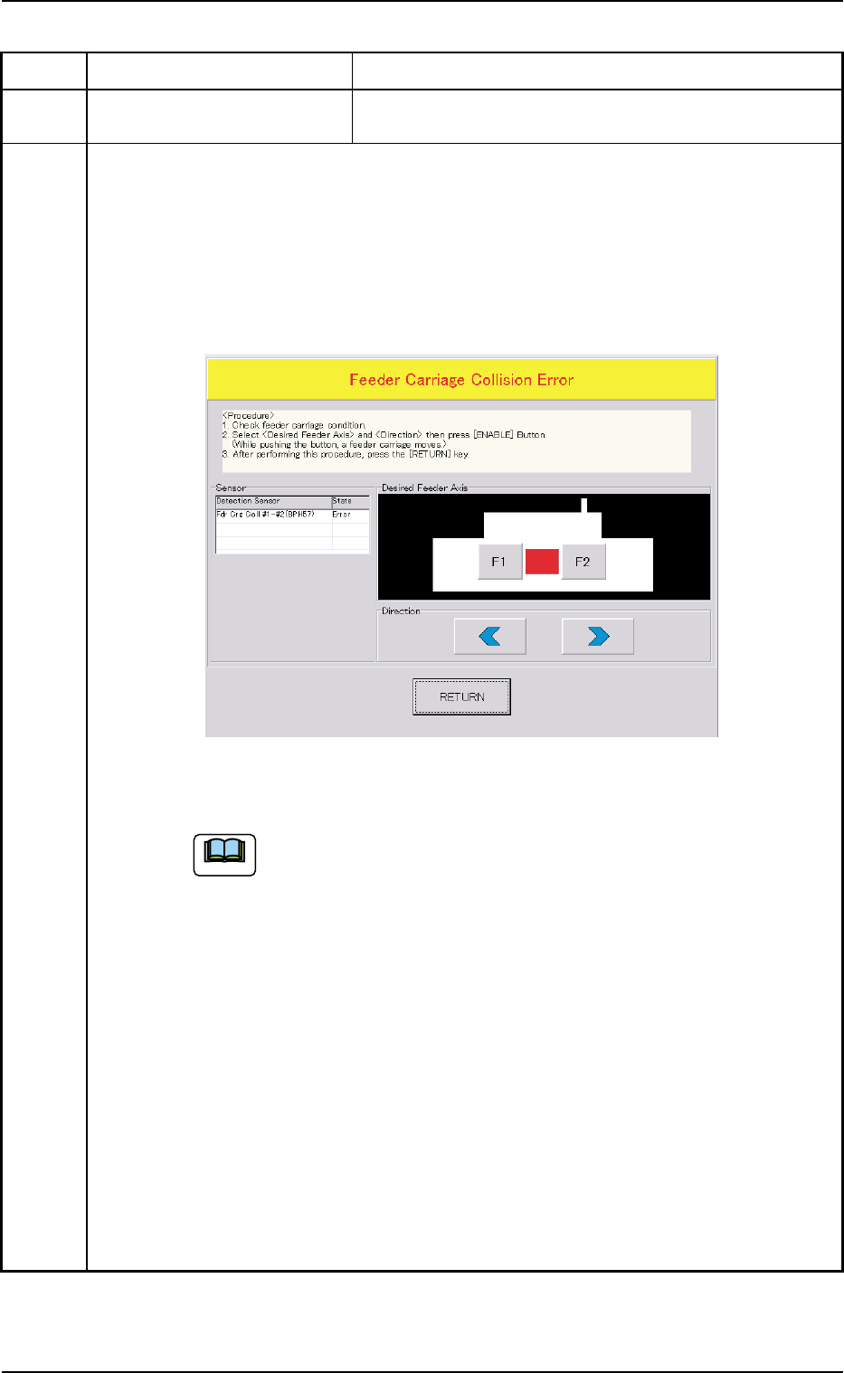
430501 Feeder Carriage Fdr.crg. axis motor #1 & #2 have collided.
(Cause 1) Dirt adheres to the sensor and the optical beam of the sensor is shielded.
(Cause 2) The sensor position may be wrong or the sensor may be defective.
The servo pack may be defective.
(Remedy 1) When the [RETURN] button is pressed, the "Feeder Carriage Collision Error"
window opens.
Follow the instructions described in this window and the procedure below for the
reset operation.
(a) When the power is re-supplied without following the correct proce-
dure to cancel the error, the feeder carriage collision error will be
detected again and the message will be issued because the contents
of the feeder carriage collision error are backed up.
(b) No zeroing operation can be performed when a feeder carriage colli-
sion error is not canceled completely.
(1) Confirm that there is no error in the feeder carriage section.
(2) Select the object feeder and the direction of the movement. After that, press
the [ENABLE] button to move the feeder carriages in separate directions.
Note: While the [ENABLE] button is held down, the feeder carriages keep
on moving.
(3) After Step (2), press the [RETURN] button.
Ref.: The original window resumes.
(4) Zero all axes and re-start the operation.
(Remedy 2) Contact our service personnel for details.
0309-002 2-102 AIL01ETRP
3.3 Error IDs and Remedial Procedures
Fig. 4B19
Note