88242361-04-01 Vol 1 DEK TQ TECHNICAL REFERENCE (1).pdfPDFA.pdf - 第113页
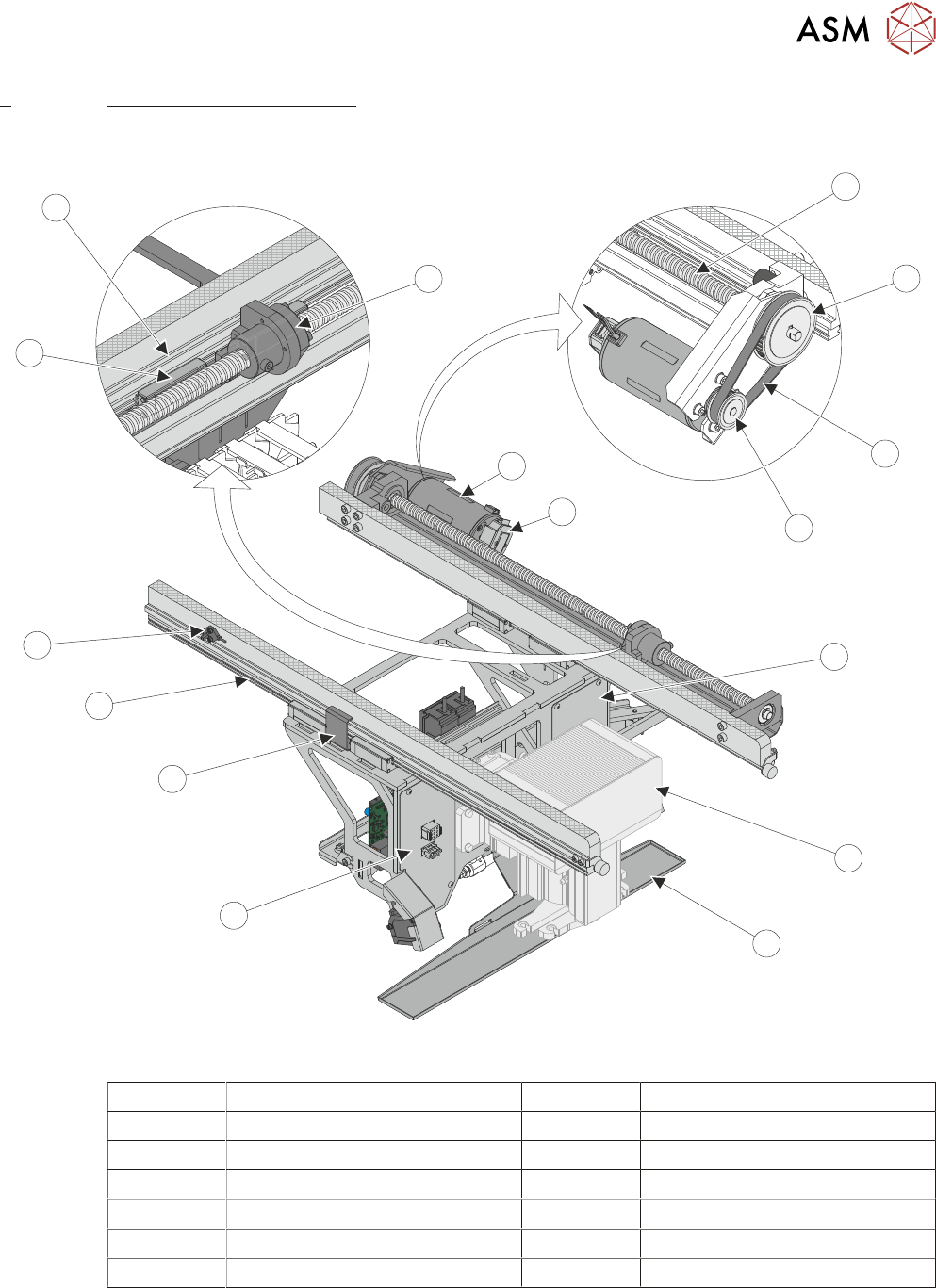
7 PRINT CARRIAGE MODULE 7.1 OVERVIEW TECHNICAL REFERENCE MANUAL DEK TQ 04/2021 113 7 PRINT CARRIAGE MODULE 7.1 OVERVIEW 7 1 2 3 7 4 6 5 9 8 1 1 12 1 1 14 10 13 Belt and Pulleys Cover removed for clarity 1 Print Carriage …

6 MACHINE CONTROL
6.5 ENCODER SERIAL INPUT OR OUTPUT (ESIO) MODULES
112 TECHNICAL REFERENCE MANUAL DEK TQ 04/2021
7 PRINT CARRIAGE MODULE
7.1 OVERVIEW
TECHNICAL REFERENCE MANUAL DEK TQ 04/2021 113
7 PRINT CARRIAGE MODULE
7.1 OVERVIEW
7
1
2
3
7
4
6
5
9
8
11
12
11
14
10
13
Belt and Pulleys Cover removed for clarity
1 Print Carriage Ball Screw 8 Squeegee Mechanism
2 Ball Screw Drive Pulley 9 Squeegee Drip Tray
3 Print Carriage Drive Belt 10 Home Sensor Vane
4 Motor Pulley 11 Linear Guide
5 Print Carriage Motor 12 Home Sensor
6 Rotary Encoder 13 Ball Screw Bearing
7 Electrical Connector Plate 14 Linear Bearing (4 Positions)
7 PRINT CARRIAGE MODULE
7.1 OVERVIEW
114 TECHNICAL REFERENCE MANUAL DEK TQ 04/2021
1
3
5
2
4
4
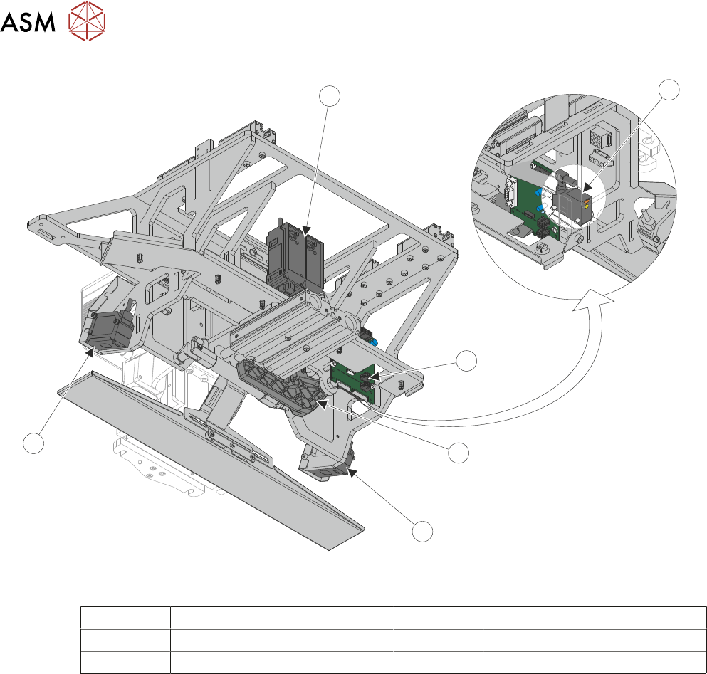
View on Rear Underneath
1 Stencil Presence Sensor 4 Auto Coplanarity Laser
2 Conditioning Board 5 Auto Coplanarity Laser Amplifiers
3 Stencil Loading Mechanism
The print carriage is a metal frame that is suspended from the top of the machine on four linear
bearings and is responsible for moving certain modules to their required positions in the Y direc-
tion. The carriage is driven by a ball screw connected to a servo motor via a drive belt. The print
carriage frame contains the following:
●
Squeegee Module - to transverse across the stencil in the Y direction (print stroke)
●
Stencil Loading Mechanism - to perform a stencil load
●
Coplanarity Lasers – to transport the auto coplanarity lasers and amplifiers to take measure-
ments from different positions
All positioning of the print carriage is referenced from the home position and calculated in the
machine software, taking into account:
●
Board width
●
Squeegee pitch
●
Hop over distance
●
Front and rear print limits
The print carriage homes during initialisation, which is carried out under the following circum-
stances:
●
At machine power up
●
After the application and recovery of the E Stop
●
When exiting machine diagnostics