88242361-04-01 Vol 1 DEK TQ TECHNICAL REFERENCE (1).pdfPDFA.pdf - 第116页
7 PRINT CARRIAGE MODULE 7.2 ELECTRICAL SCHEMATIC 116 TECHNICAL REFERENCE MANUAL DEK TQ 04/2021 7.2 ELECTRICAL SCHEMATIC Machine Controller Controller Power Module (C P M) Fibre Optic Links Ribbon Cables S IO Link Cable M…
7 PRINT CARRIAGE MODULE
7.1 OVERVIEW
TECHNICAL REFERENCE MANUAL DEK TQ 04/2021 115
An extendible squeegee drip tray mechanism is incorporated into the carriage. For information on
the squeegee drip tray, refer to 8
"SQUEEGEE MODULE" [}123].
For Information on the stencil loading mechanism, and stencil detection sensor, refer to 10 "STEN-
CIL ALIGNMENT MODULE" [}165].
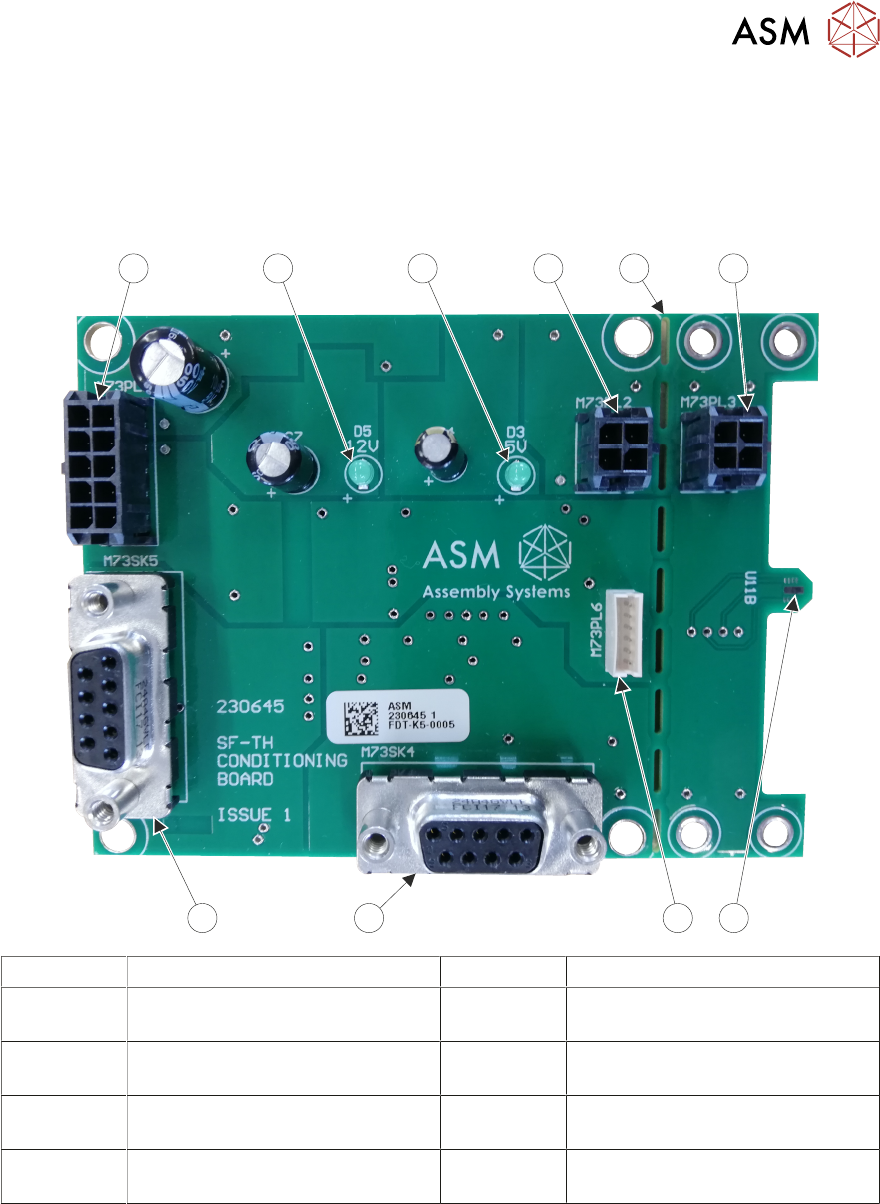
7.1.1 Conditioning Board
1 2 3
456
7
8 9
10
1 Extension Lead Connector 6 Squeegee Load Cell Connector
2 Extension Board Break-Off Point 7 Analogue I/O to ESIO Upper
Frame 3
3 Extension Lead Connector 8 Digital I/O to ESIO Breakout
Board Upper Frame 1A
4 Temperature & Humidity Sensor
(on the underside of the board)
9 12 Volt LED Indicator
5 Programming Connector
(Not Used)
10 5 Volt LED Indicator
The conditioning board is located at the rear of the print carriage. It features an on-board temperat-
ure and humidity sensor. The temperature and humidity is monitored in the print area and dis-
played to the operator on the screen.
A break-off section of the board can be separated from the main board, connected using an exten-
sion cable and positioned at the customers discretion.
The board is supplied with 24 volts to the Digital I/O connector. On-board regulators reduce the
voltage to 12V and 5V.
The conditioning board also contains the electronics for the squeegee strain gauge mechanism,
supplying software with feedback on squeegee pressure.
7 PRINT CARRIAGE MODULE
7.2 ELECTRICAL SCHEMATIC
116 TECHNICAL REFERENCE MANUAL DEK TQ 04/2021
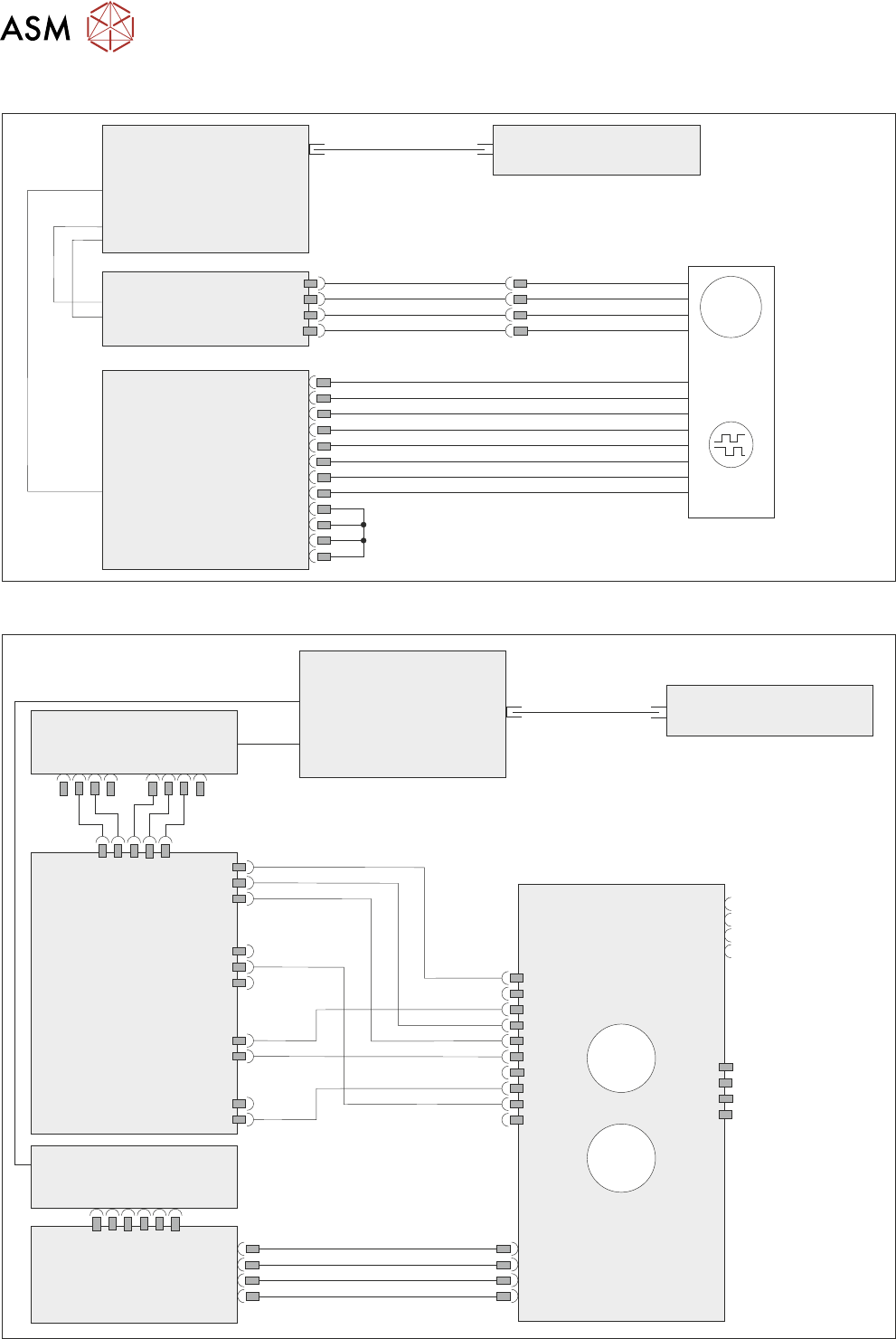
7.2 ELECTRICAL SCHEMATIC
Machine Controller
Controller Power Module
(CPM)
Fibre Optic Links
Ribbon Cables
SIO Link Cable
M
Print
Carriage
Drive Motor
MTR17
Extended Power Module
EPM3-1
J3
EPM3PL11
Print
Carriage
Encoder
4ENC3
ESIO-4
ENC3
7.2.1 Conditioning Board
Machine Controller
Controller Power Module
(CPM)
Fibre Optic Links
SIO Link
Cables
ESIO-5
ESIO-3
ESIO-3: Breakout A
ADC/DAC
Board 5
Conditioning Board
IO4 IO5
3ASK2
M73PL5
5PL3
M73SK1
3ASK23
3ASK24
3ASK13
3ASK14
M73SK4
M73PL2
Connector for
break-off
temperature and
humidity board
Connector for
squeegee load cell
°C
%RH
7 PRINT CARRIAGE MODULE
7.3 CALIBRATIONS
TECHNICAL REFERENCE MANUAL DEK TQ 04/2021 117
7.3 CALIBRATIONS
7.3.1 Print Carriage Home Offset
WARNING
BOARD CLAMPS. EXTREME CARE MUST BE EXERCISED WHEN WORKING IN
THE TOOLING AREA OF THE MACHINE TO AVOID INJURY. THE FOILS ON THE
FRONT AND REAR BOARD CLAMPS ARE VERY SHARP.
Before starting this procedure, ensure the stencil is removed from the machine.
To calibrate the print carriage home offset, carry out the following:
1. Select Menu.
2. Select Service\Calibration.
3. Select Print Carriage Home Offset.
4. The print carriage moves to the previous print carriage home offset position and the convey-
ors lift to print height.
5. Open the front cover.