88242361-04-01 Vol 1 DEK TQ TECHNICAL REFERENCE (1).pdfPDFA.pdf - 第166页
10 STENCIL ALIGNMENT MODULE 10.1 OVERVIEW 166 TECHNICAL REFERENCE MANUAL DEK TQ 04/2021 10.1.1 Chase The chase is a free-floating assembly providing a receptacle for the stencil which can be moved and rotated horizontall…
10 STENCIL ALIGNMENT MODULE
10.1 OVERVIEW
TECHNICAL REFERENCE MANUAL DEK TQ 04/2021 165
10 STENCIL ALIGNMENT MODULE
10.1 OVERVIEW
11
10
9
8
7
6
5
4
4
3
3
3
2
2
1
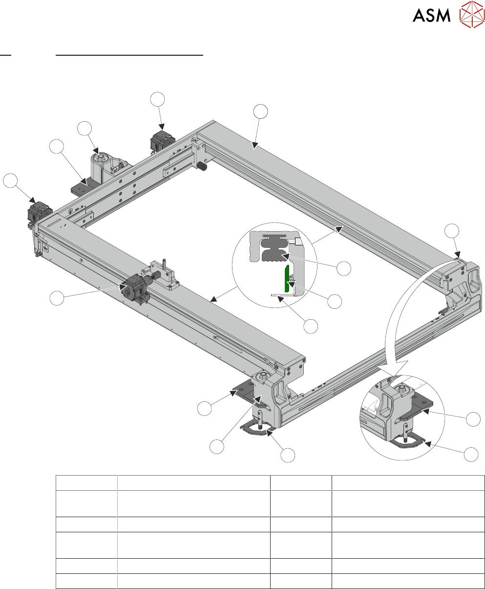
1 Chase Assembly 7 Stencil Support Plate
2 Front Roller Ball and Chase
Clamp
8 X Alignment Actuator
3 Roller Plate 9 Left Y Alignment Actuator
4 Chase Movement Limiter 10 Rear Roller Ball and Chase
Clamp
5 Pneumatic Stencil Clamp 11 Right Y Alignment Actuator
6 Stencil Guide Strip
The stencil alignment module is one of the most critical components of machine accuracy. This
module consists of the following linked systems:
●
Chase Assembly
●
Alignment Actuators
●
Stencil Load Mechanism
●
Stencil Clamps
●
Chase Clamps
●
Coplanarity
10 STENCIL ALIGNMENT MODULE
10.1 OVERVIEW
166 TECHNICAL REFERENCE MANUAL DEK TQ 04/2021
10.1.1 Chase
The chase is a free-floating assembly providing a receptacle for the stencil which can be moved
and rotated horizontally to align perfectly with the product board.
The stencil is loaded from the front of the machine and slid into the chase along the top of stencil
supports. A sprung stencil location guide strip (located in the right hand side of the chase assem-
bly) ensures the stencil is pushed against the opposite, fixed stencil guide strip. The stencil is
clamped in the chase using a pair of pneumatically operated stencil clamps.
The chase is correctly aligned by three actuators and software calculates the direction and distance
that each actuator must move to align the stencil to the board. Once correctly aligned, the chase is
clamped in place by three pneumatic chase clamps.
Chase movement limiters on either side of the front of the chase prevent over-adjustment of the
chase which could lead to collisions between the chase and machine’s frame or other modules.
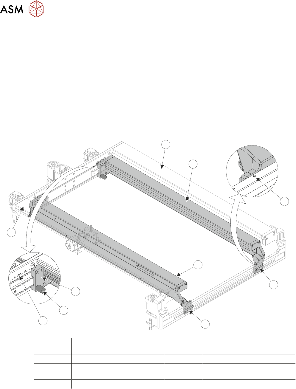
10.1.1.1 Adjustable Stencil Holder
7
6
5
4
4
3
2
2
1
1
1 Chase Frame 5 Rear Stencil Width Adjustment
(2 Positions)
2 Adjustable Stencil Holder 6 Rear Stencil Stop
3 Front Stencil Width Measuring
Scale (2 Positions)
7 Rear Stencil Width Measuring
Scale (2 Positions)
4 Front Stencil Width Adjustment
10 STENCIL ALIGNMENT MODULE
10.1 OVERVIEW
TECHNICAL REFERENCE MANUAL DEK TQ 04/2021 167
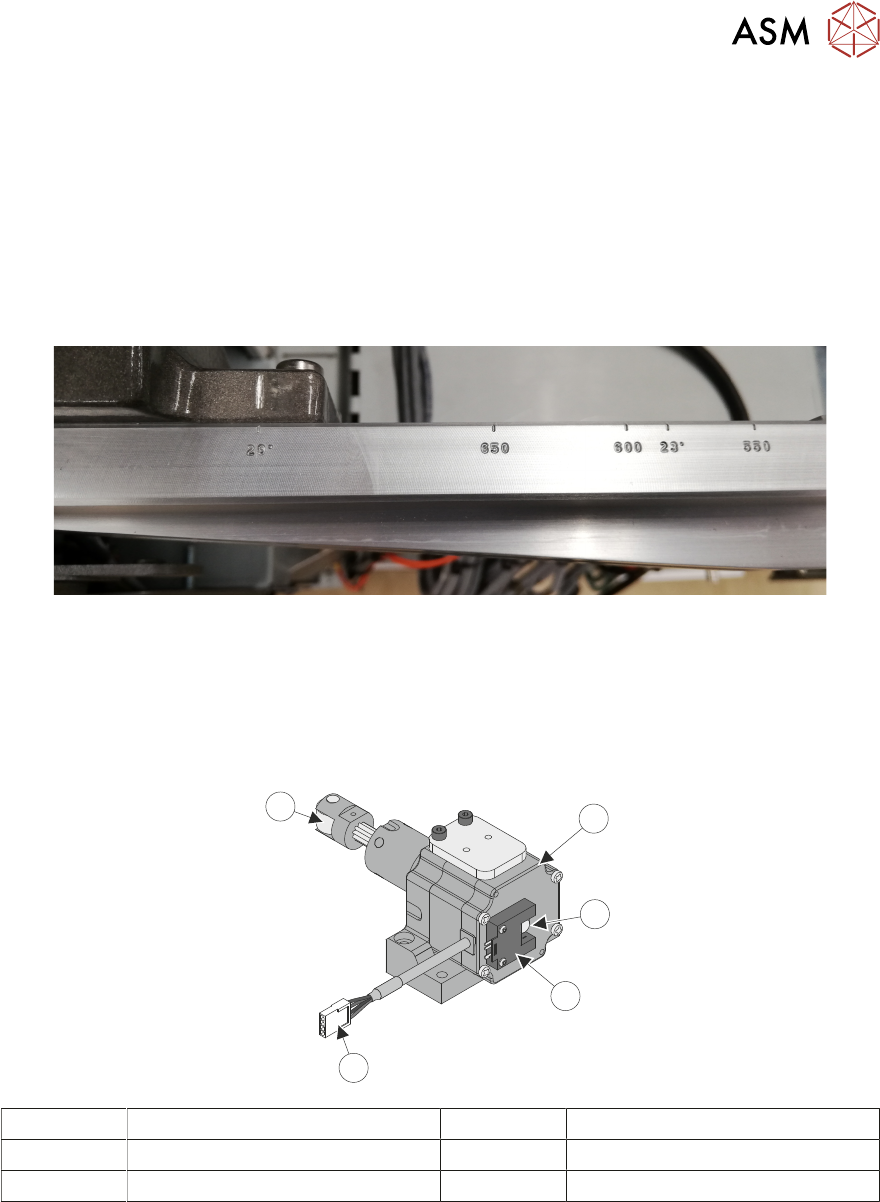
The chase width is adjustable and can be set to accommodate stencil sizes from 29” (736.6mm) to
550mm. The following most common sized stencils used are engraved on the front and rear of the
chase frame:
●
29” (736.6mm)
●
650mm
●
600mm
●
23” (584.2mm)
●
550mm
NOTE
To prevent a collision with the drip tray a short drip tray (360mm) should be used in conjunction
with a stencil size of 620mm (24.409") or less.
The stencil frame thickness is 25 to 40mm without the stencil clamp adapter.
10.1.2 Alignment Actuators
1
3
4
2
5
1 Alignment Actuator Motor 4 Electrical Connection
2 Alignment Actuator Plunger 5 Contact Roller
3 Home Sensor
The actuators are configured in a three-point contact arrangement and are controlled and driven in-
dependently to give maximum flexibility in stencil movement in the X, Y and Theta.
A spring fitted between the machine frame and the chase ensures that the chase is pulled against
the actuator rollers at all times.