88242361-04-01 Vol 1 DEK TQ TECHNICAL REFERENCE (1).pdfPDFA.pdf - 第133页
8 SQUEEGEE MODULE 8.3 ADJUSTMENTS AND SETTINGS TECHNICAL REFERENCE MANUAL DEK TQ 04/2021 133 6. Select Print Carriage . 7. Select Carriage To Rear . 8. Select Front Squegee . 9. Turn the monitor so that it can be viewed …
8 SQUEEGEE MODULE
8.3 ADJUSTMENTS AND SETTINGS
132 TECHNICAL REFERENCE MANUAL DEK TQ 04/2021
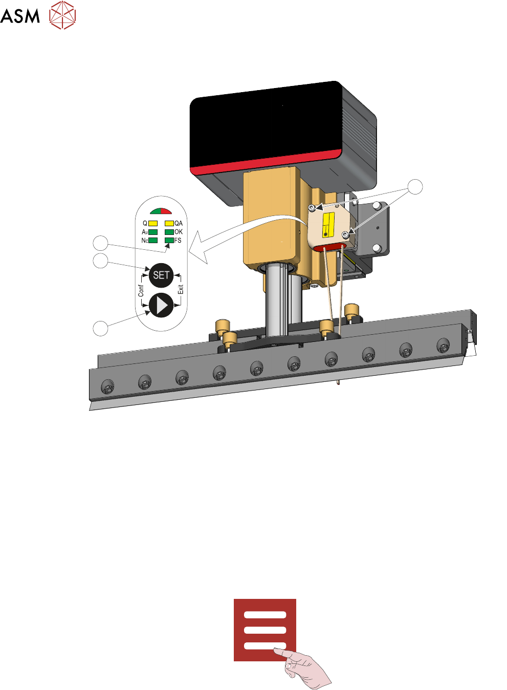
8. Using a 3mm Allen key, remove the two securing screws (1) that secure the sensor to the
bracket.
Laser
1
IEC 60825-1:2014
1
4
3
2
9. Press and hold the arrow button (2) until the FS LED (4) lights.
10. Press the SET button (3).
11. Refit the sensor to the bracket.
12. Close the front cover.
13. Reset the E Stop.
14. Press the System button.
15. Select Reinitialise.
8.3.2 Drip Tray Retracted Sensor
If replacing the drip tray retracted sensor, use the following procedure to set the correct position:
1. Select Menu.
2. Select Service\Diagnostics.
3. Select Confirm.
4. Select Front or Rear Squeegee.
5. Toggle the Drip Tray Extended switch to 0, ensuring that the drip tray retracted sensor I/O is
ON
(green).
8 SQUEEGEE MODULE
8.3 ADJUSTMENTS AND SETTINGS
TECHNICAL REFERENCE MANUAL DEK TQ 04/2021 133
6. Select Print Carriage.
7. Select Carriage To Rear.
8. Select Front Squegee.
9. Turn the monitor so that it can be viewed from the rear of the machine.
10. Remove the upper rear panel.
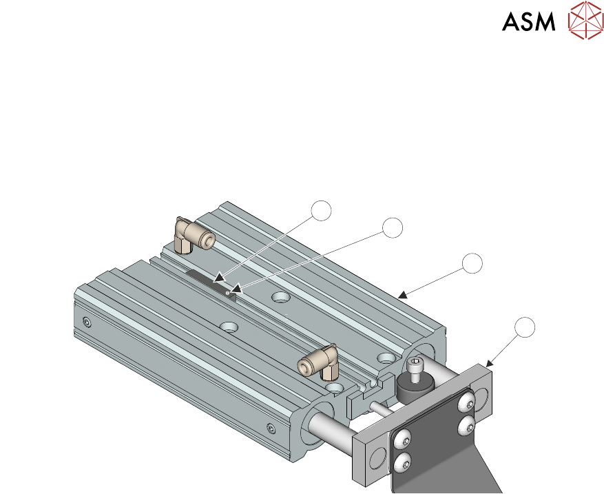
11. Mark the position of the current sensor (1).
2
1
3
4
12. Loosen the screw (2) on the sensor and retract from the drip tray pneumatic actuator (3).
13. Disconnect the sensor plug 4PL22.
14. Connect the new sensor.
15. Fit the sensor in the drip tray pneumatic actuator up to the mark created in Step 10.
16. Viewing the monitor, ensure that the drip tray retracted sensor is ON (green).
17. Move the drip tray piston (4) manually out and in multiple times ensuring the drip tray retrac-
ted sensor switches off and on. Adjust the position of the sensor if necessary.
18. Tighten the sensor screw.
19. Refit the upper rear panel.
20. Select Exit.
21. Select Accept.
8 SQUEEGEE MODULE
8.4 CALIBRATIONS
134 TECHNICAL REFERENCE MANUAL DEK TQ 04/2021
8.4 CALIBRATIONS
8.4.1 Squeegee Load Cell
WARNING
BOARD CLAMPS. EXTREME CARE MUST BE EXERCISED WHEN WORKING IN
THE TOOLING AREA OF THE MACHINE TO AVOID INJURY. THE FOILS ON THE
FRONT AND REAR BOARD CLAMPS ARE VERY SHARP.
Squeegee pressure calibration is carried out on machines after the following circumstances:
●
The squeegee mechanism is replaced
●
The strain gauge bridge in the squeegee mechanism is replaced
●
On suspicion that the squeegee pressure is incorrect.
A force meter calibration jig and pressure plate are required to perform the squeegee pressure cali-
bration.
Use the following procedure to calibrate the squeegee pressure:
1. Select Unload Stencil.
2. Open the front cover.
3. Remove the stencil.
4. Remove the squeegees.
5. Remove the tooling from the tooling table.
6. Close the front cover.
7. Press the System button.
8. Select Menu.
9. Select Service\Calibration.
10. Select Squeegee Load Cell.
The conveyors are checked for the presence of a board, the print carriage moves to the cali-
bration position, the rear conveyor is driven to 200mm
board width and the table homes.
The Front and Rear Squeegee Load Cell Calibration screens are displayed.
11. Select Calibrate Front.
12. Open the front cover.