88242361-04-01 Vol 1 DEK TQ TECHNICAL REFERENCE (1).pdfPDFA.pdf - 第88页
6 MACHINE CONTROL 6.5 ENCODER SERIAL INPUT OR OUTPUT (ESIO) MODULES 88 TECHNICAL REFERENCE MANUAL DEK TQ 04/2021 6.5 ENCODER SERIAL INPUT OR OUTPUT (ESIO) MODULES The ESIO modules connect to the CPM using serial cable an…
6 MACHINE CONTROL
6.4 EXTENDED POWER MODULE (EPM)
TECHNICAL REFERENCE MANUAL DEK TQ 04/2021 87
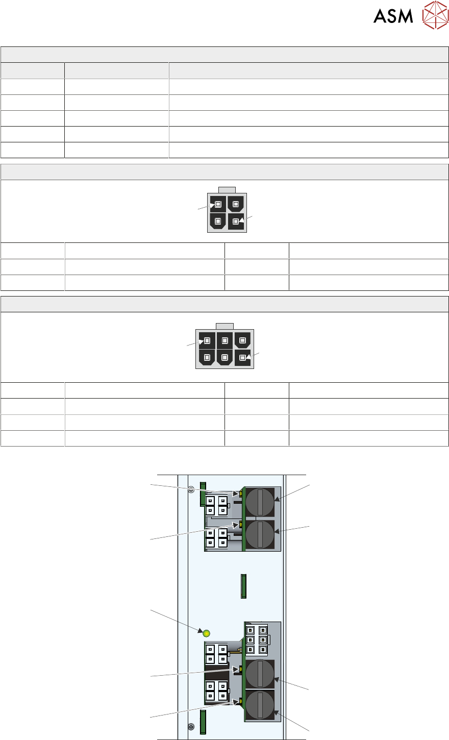
EPM 3 Lower
Connector Fuse Description
J2-1 F2-1 (5A) Camera Y Linear Drive
J2-2 F2-2 (2A) Under Stencil Cleaner Y Linear Drive
J2-3 F2-3 (2A) Conveyor Width Left Linear Drive (APC Conveyors)
J2-4 F2-4 (2A) Conveyor Width Right Linear Drive (APC Conveyors)
J2-5 Power Input
J*-1, J*-2, J*-3 and J*-4
1
4
Pin No Signal Pin No Signal
1 MTR Phase R 3 MTR Phase S
2 Earth 4 MTR Phase T
J*-5
1
6
Pin No Signal Pin No Signal
1 48V SW 4 48V SW
2 0V 5 0V
3 Not Used 6 24V US
6.4.2.2 LEDs
LED 1
LED 2
24V
Logic
LED 3
LED 4
F*-3
F*-1
F*-4
F*-2
Each output has its own fuse and indicator LED. If a fuse is blown, the LED is dimmed.
6 MACHINE CONTROL
6.5 ENCODER SERIAL INPUT OR OUTPUT (ESIO) MODULES
88 TECHNICAL REFERENCE MANUAL DEK TQ 04/2021
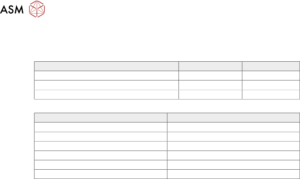
6.5 ENCODER SERIAL INPUT OR OUTPUT (ESIO) MODULES
The ESIO modules connect to the CPM using serial cable and are located close to the mechanical
module that they relate to. There are three different types of ESIO modules located around the
machine:
ESIO 12 ESIO 15
Digital Input and Output Ports 24 16
Encoder Ports 4 2
ADC and DAC Ports 0 1
The following table indicates what type of ESIO is used:
Item Type
ESIO-1 ESIO 12
ESIO-2 ESIO 15
ESIO-3 ESIO 12
ESIO-4 ESIO 12
ESIO-5 ESIO 15
ESIO-6 ESIO 15
6 MACHINE CONTROL
6.5 ENCODER SERIAL INPUT OR OUTPUT (ESIO) MODULES
TECHNICAL REFERENCE MANUAL DEK TQ 04/2021 89
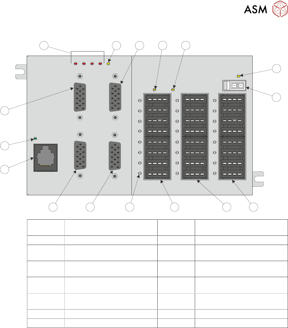
6.5.1 ESIO 12
IO1
IO2
IO3
IO4
IO5
IO6
IO7
IO8
IO9
IO10
IO11
IO12
IO13
IO14
IO15
IO16
IO17
IO18
IO19
IO20
IO21
IO22
IO23
IO24
ENC4 ENC2
ENC3 ENC1
+24V3 +24V2
+24V1
ENCFAULT
4 3 2 1 +5V
16
15
141312
11
10
9
8
7
6
5
3
4
2
1
1 24V Supply LED for Bank 1 9 RJ11 Serial Connection from the
CPM (SIOLink)
2 24V Power Supply Input 10 SIOLink Status LED
3 Digital Inputs and Outputs Bank 1
(IO1 to IO8)
11 Encoder Input (ENC3)
4 Digital Inputs and Outputs Bank 2
(IO9 to IO16)
12 ENC Fault LEDs
5 Digital Inputs and Outputs Bank 3
(IO17 to IO24)
13 Internal 5V Status LED
6 Digital Input and Output Status
LED (24 positions)
14 Encoder Input (ENC1)
7 Encoder Input (ENC2) 15 24V Supply LED for Bank 3
8 Encoder Input (ENC4) 16 24V Supply LED for Bank 2