88242361-04-01 Vol 1 DEK TQ TECHNICAL REFERENCE (1).pdfPDFA.pdf - 第91页
6 MACHINE CONTROL 6.5 ENCODER SERIAL INPUT OR OUTPUT (ESIO) MODULES TECHNICAL REFERENCE MANUAL DEK TQ 04/2021 91 ENC1 to ENC4 10 1 5 1 1 Pin No Signal Pin No Signal 1 CHA+ 9 CHA- 2 N/C 10 N/C 3 CHB+ 11 CHB- 4 5V 12 N/C 5…
6 MACHINE CONTROL
6.5 ENCODER SERIAL INPUT OR OUTPUT (ESIO) MODULES
90 TECHNICAL REFERENCE MANUAL DEK TQ 04/2021
6.5.1.1 Status LEDs
The ESIO modules are fitted with a number of LEDs which give indication of the status of the
power supplied to the module and the input/outputs connected to it. The following table details the
LEDs and their function:
LED Description Colour ON OFF
SIOLink Indicates status of SIOLink to
CPM module
Green Linked Not Linked
Encoders 1 to 4 Indicates there is an error with
the encoder or it is disconnected
Red Fault No Fault
5V supply Indicates status of internal 5V
supply
Yellow OK Not OK
24V Supply Indicates status of 24V supply to
the Digital IO banks
Yellow OK Not OK
IO 1 to 24 Indicates activity status of inputs Green Active Inactive
Indicates activity status of outputs Red Active Inactive
Indicates current overload has
been detected
Red Flashing
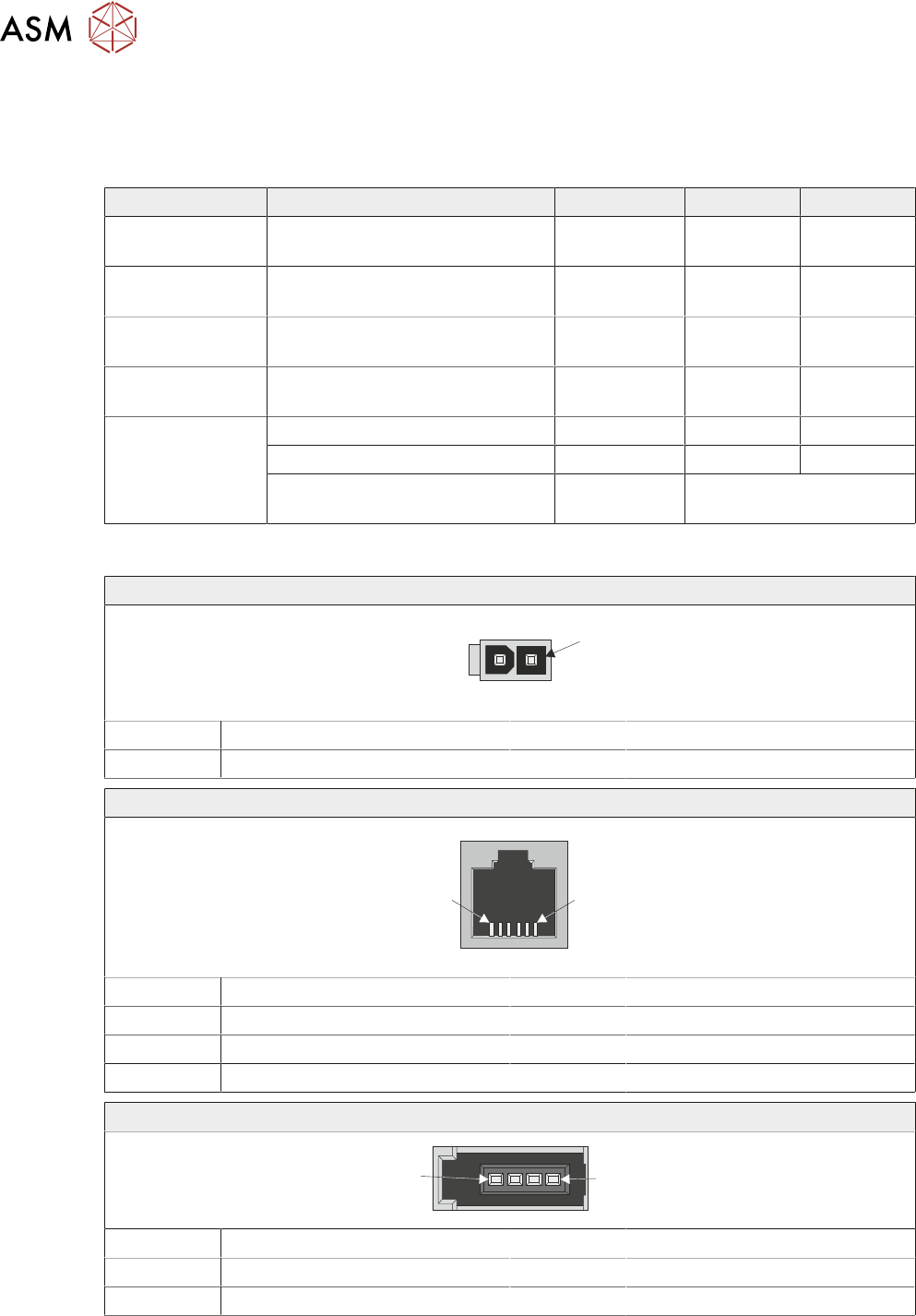
6.5.1.2 Connectors
24V Power Supply Input
1
Pin No Signal Pin No Signal
1 24V 2 0V
SIOLink
1
6
Pin No Signal Pin No Signal
1 Not Used 4 XCVR-
2 GND 5 Not Used
3 XCVR+ 6 GND
Digital Input and Output (IO1 to IO24)
1
4
Pin No Signal Pin No Signal
1 24V 3 Input
2 Output 4 0V
6 MACHINE CONTROL
6.5 ENCODER SERIAL INPUT OR OUTPUT (ESIO) MODULES
TECHNICAL REFERENCE MANUAL DEK TQ 04/2021 91
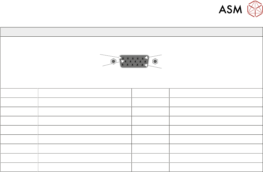
ENC1 to ENC4
10
1
5
11
Pin No Signal Pin No Signal
1 CHA+ 9 CHA-
2 N/C 10 N/C
3 CHB+ 11 CHB-
4 5V 12 N/C
5 0V 13 N/C
6 LMT 14 CHC+
7 CHC- 15 N/C
8 HOME
6 MACHINE CONTROL
6.5 ENCODER SERIAL INPUT OR OUTPUT (ESIO) MODULES
92 TECHNICAL REFERENCE MANUAL DEK TQ 04/2021
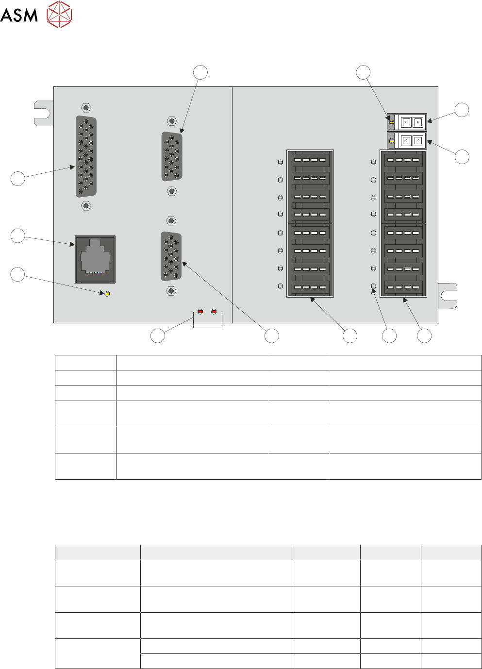
6.5.2 ESIO 15
IO1
IO2
IO3
IO4
IO5
IO6
IO7
IO8
ENC2
ENC1
24VIO
ENCFAULT
21
GLink
24VL
IO9
IO10
IO11
IO12
IO13
IO14
IO15
IO16
12
11
10
9
8 7
6
5
4
3
2
1
1 24V LED (2 positions) 7 Encoder Input (ENC2)
2 24V Supply for Outputs 8 ENC Fault LEDs
3 24V Supply 9 Serial Link Status LED
4 Digital Inputs and Outputs Bank 1
(IO1 to IO8)
10 RJ11 Serial Connection from the
CPM (SIOLink)
5 Digital Input and Output Status
LED (16 positions)
11 Analogue Inputs and Outputs
(ADC/DAC)
6 Digital Inputs and Outputs Bank 2
(IO9 to IO16)
12 Encoder Input (ENC1)
6.5.2.1 Status LEDs
The ESIO module is fitted with a number of LEDs which give indication of the status of the power
supplied to the module and the input/outputs connected to it. The following table details the LEDs
and their function:
LED Description Colour ON OFF
SIOLink Indicates status of SIOLink to
CPM module
Green Linked Not Linked
Encoders 1 and 2 Indicates there is an error with
the encoder or it is disconnected
Red Fault No Fault
24V Supply Indicates status of 24V supply to
the Digital IO banks
Yellow OK Not OK
IO 1 to 16 Indicates activity status of inputs Green Active Inactive
Indicates activity status of outputs Red Active Inactive