88242361-04-01 Vol 1 DEK TQ TECHNICAL REFERENCE (1).pdfPDFA.pdf - 第70页
5 POWER SUPPLY 5.4 POWER MONITORING 70 TECHNICAL REFERENCE MANUAL DEK TQ 04/2021

5 POWER SUPPLY
5.4 POWER MONITORING
TECHNICAL REFERENCE MANUAL DEK TQ 04/2021 69
Each circuit breaker has two channels, measuring the voltage before and after the circuit breaker.
Each channel displays the minimum, maximum and nominal voltages since the machine was last
powered up or Refresh Values was selected. The channel is displayed in red if the voltage is cur-
rently out of tolerance, amber if the voltage has previously been out of tolerance or green if the
voltage is and has stayed within tolerance.
Selecting a circuit breaker on the screen displays more information on that breaker in the bottom
left of the screen.

5 POWER SUPPLY
5.4 POWER MONITORING
70 TECHNICAL REFERENCE MANUAL DEK TQ 04/2021
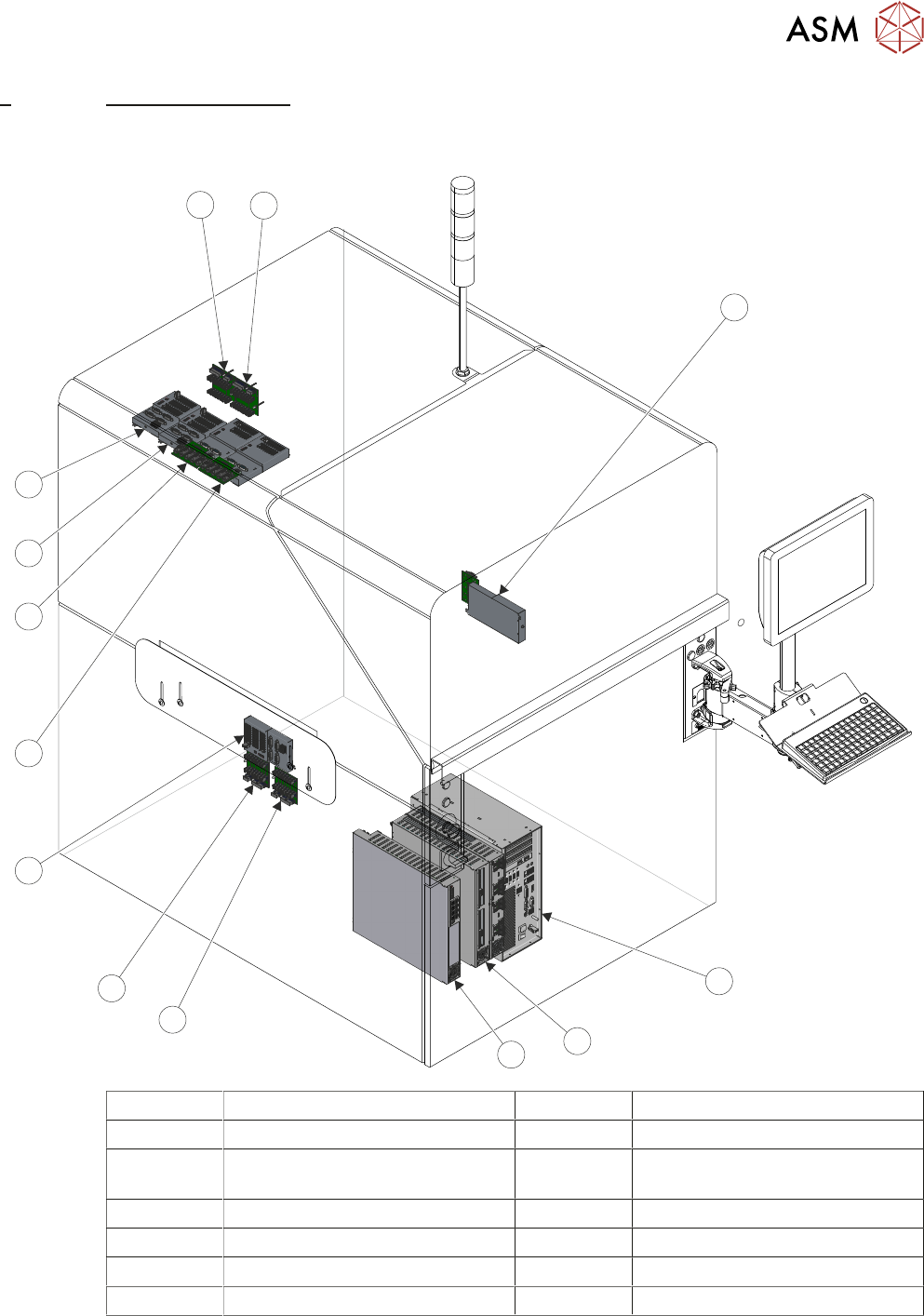
6 MACHINE CONTROL
6.1 OVERVIEW
TECHNICAL REFERENCE MANUAL DEK TQ 04/2021 71
6 MACHINE CONTROL
6.1 OVERVIEW
1
2
3
4
5
6
7
8
9
10
11
12
13
1 ESIO-2 & ADC 8 ESIO-6 & ADC (Optional)
2 Machine Controller (PC) 9 ESIO-5 & ADC
3 EPMs (2 or 3 depending on op-
tions)
10 ESIO-4
4 CPM 11 ESIO-3
5 ESIO-1: Breakout B 12 ESIO-3: Breakout A
6 ESIO-1: Breakout A 13 ESIO-3: Breakout B
7 ESIO-1