88242361-04-01 Vol 1 DEK TQ TECHNICAL REFERENCE (1).pdfPDFA.pdf - 第180页
10 STENCIL ALIGNMENT MODULE 10.3 ADJUSTMENTS AND SETTINGS 180 TECHNICAL REFERENCE MANUAL DEK TQ 04/2021 10.3.2 Stencil Clamp Regulator To set the pressure on the stencil clamp regulator, refer to the Adjustment and Setti…
10 STENCIL ALIGNMENT MODULE
10.3 ADJUSTMENTS AND SETTINGS
TECHNICAL REFERENCE MANUAL DEK TQ 04/2021 179
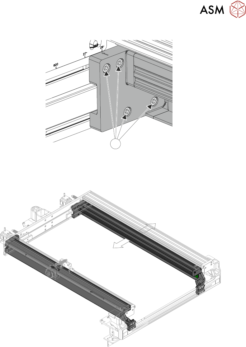
7. Loosen the four securing screws (1) that secure the adjustable stencil holder at the rear.
1
8. Repeat Steps 6 and 7 for the left hand side.
9. On the right hand side, slide the stencil holder to the required position using the etched di-
mension marker on the chase frame. Ensure that the pneumatic tube at the rear does not
snag.
10. Secure (but do not tighten) one of the screws at the rear.
11. Check that the front is aligned to the etched dimension marker on the chase frame and secure
(but do not tighten) one of the screws.
12. Repeat Steps 9 to 11 for the left hand side.
13. On the rear left hand side, tighten the four securing screws to 10.5Nm ±0.5Nm. Do not over-
tighten.
14. Loosen the securing screw at the front to ensure there is no tension forcing the chase holder
to the left or the right.
15. On the front left hand side, tighten the four securing screws to 10.5Nm ±0.5Nm. Do not over-
tighten.
16. Repeat Steps 13 to 15 for the right hand side.
17. Secure any surplus tubing in the clip and secure the clip.
18. Refit the upper rear panel.
10 STENCIL ALIGNMENT MODULE
10.3 ADJUSTMENTS AND SETTINGS
180 TECHNICAL REFERENCE MANUAL DEK TQ 04/2021
10.3.2 Stencil Clamp Regulator
To set the pressure on the stencil clamp regulator, refer to the Adjustment and Settings section of
the Pneumatics chapter, Volume 2.
10.3.3 Stencil Presence Sensor
To adjust the stencil presence sensor, carry out the following procedure:
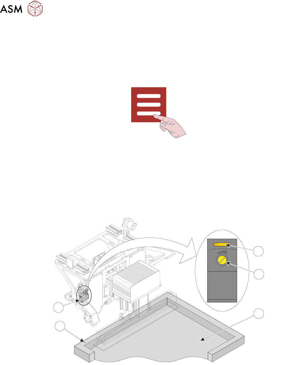
1. Select Menu.
2. Select Service\Diagnostics.
3. Select Confirm.
4. Select Print Carriage.
5. Select Carriage To Front.
6. Toggle Stencil Detector to On.
7. Open the front cover.
8. Position a stencil in the machine so the rear stencil frame is beneath the stencil presence
sensor (5). A red laser dot (4) is visible on the stencil frame (3).
1
4
3
2
5
9. Using a potentiometer trimming tool, adjust the sensor sensitivity (2) anti-clockwise until the
sensor test LED (1) extinguishes.
10. Turn the sensor sensitivity clockwise until the sensor test LED switches On.
11. Turn the sensor sensitivity clockwise a further half-turn.
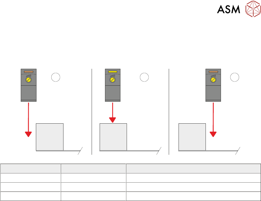
12. Move the rear stencil frame backwards and forwards under the sensor to ensure that the test
LED is only activated by the stencil frame (see diagram at end of procedure).
13. Remove the stencil.
14. Close the front cover.
10 STENCIL ALIGNMENT MODULE
10.3 ADJUSTMENTS AND SETTINGS
TECHNICAL REFERENCE MANUAL DEK TQ 04/2021 181
15. Press the System button.
16. Toggle Stencil Detector to OFF.
17. Select Exit.
18. Select Accept.
1 2
3
Item LED Sensor Position
1 Off Sensor behind the stencil
2 On Sensor over the stencil frame
3 Off Sensor over the stencil