88242361-04-01 Vol 1 DEK TQ TECHNICAL REFERENCE (1).pdfPDFA.pdf - 第16页
2 SAFETY FEATURES 2.3 SAFETY CIRCUIT 16 TECHNICAL REFERENCE MANUAL DEK TQ 04/2021 2.3 SAFETY CIRCUIT 1 2 3 4 5 6 8 7 1 Front Cover Safety Switch 5 Mains Isolator Switch 2 Right Jog Button 6 Emergency Stop (E Stop) Button…
2 SAFETY FEATURES
2.2 SAFETY NOTICES
TECHNICAL REFERENCE MANUAL DEK TQ 04/2021 15
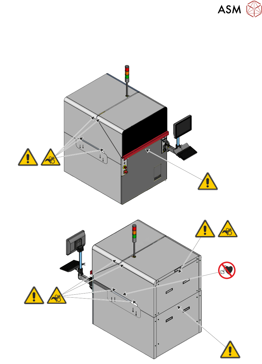
2.2.5 Warning Labels
Warning labels are placed on the machine covers and components to alert personnel to possible
hazards which may cause physical injury or machine damage. The following graphics depict the
location of warning labels fitted to the machine covers:
2 SAFETY FEATURES
2.3 SAFETY CIRCUIT
16 TECHNICAL REFERENCE MANUAL DEK TQ 04/2021
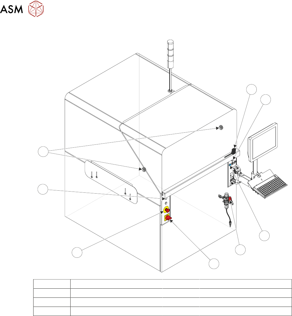
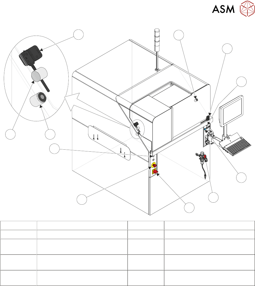
2.3 SAFETY CIRCUIT
1
2
3
4
5
6
8
7
1 Front Cover Safety Switch 5 Mains Isolator Switch
2 Right Jog Button 6 Emergency Stop (E Stop) Button
3 System Button 7 Left Jog Button
4 Pneumatic Lockout 8 Electromagnetic Cover Locks
2 SAFETY FEATURES
2.3 SAFETY CIRCUIT
TECHNICAL REFERENCE MANUAL DEK TQ 04/2021 17
9
8
8
7
6
5
4
3
2
1
10
1 Front Cover Safety Switch 6 Emergency Stop (E Stop) Button
2 Right Jog Button 7 Left Jog Button
3 System Button 8 Electromagnetic Front Cover
Locks
4 Pneumatic Lockout 9 Electromagnetic Paste Dispenser
Cover Lock
5 Mains Isolator Switch 10 Paste Dispenser Cover Safety
Switch
The safety circuit ensures that the printer is in a safe condition before the printer can operate. In
the event of the safety circuit being interrupted, switched power is disconnected from all motors
and some pneumatic solenoids preventing any hazardous movement within the printer.
The safety circuit consists of the E Stop button and the front cover safety switch. With the safety
components in a safe state, the safety relay allows power to the motors and I/O by pressing the
system button.