88242361-04-01 Vol 1 DEK TQ TECHNICAL REFERENCE (1).pdfPDFA.pdf - 第35页
4 MACHINE OVERVIEW 4.1 MODULE OVERVIEWS TECHNICAL REFERENCE MANUAL DEK TQ 04/2021 35 4.1.4.3 Paste Roll Height Laser The paste roll height laser measures the height of the paste roll in front of the front squeegee dur- i…
4 MACHINE OVERVIEW
4.1 MODULE OVERVIEWS
34 TECHNICAL REFERENCE MANUAL DEK TQ 04/2021
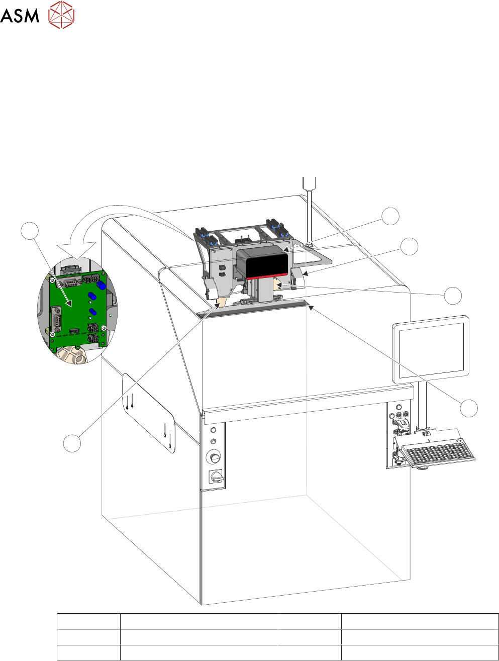
4.1.4 Print Carriage Module
The print carriage is the vehicle that transports the following:
●
Squeegee Module
●
Squeegee Drip Tray
●
Stencil Load Mechanism
●
Paste Roll Height Laser
●
Coplanarity Lasers
●
Temperature and Humidity Sensors
6
5
4
3
2
1
1 Squeegee Mechanism 4 Squeegee Drip Tray
2 Coplanarity Laser (in 2 positions) 5 Stencil Load Paddle
3 Paste Roll Height Laser 6 Temperature and Humidity Board
4.1.4.1 Squeegee Module
The function of the squeegee module is to apply the print material through the stencil image onto
the board in a controlled manner. Squeegee downward pressure is monitored during the print
stroke to optimize the print quality.
4.1.4.2 Stencil Load Mechanism
The stencil load mechanism automatically loads the stencil to the correct position in the chase.

4 MACHINE OVERVIEW
4.1 MODULE OVERVIEWS
TECHNICAL REFERENCE MANUAL DEK TQ 04/2021 35
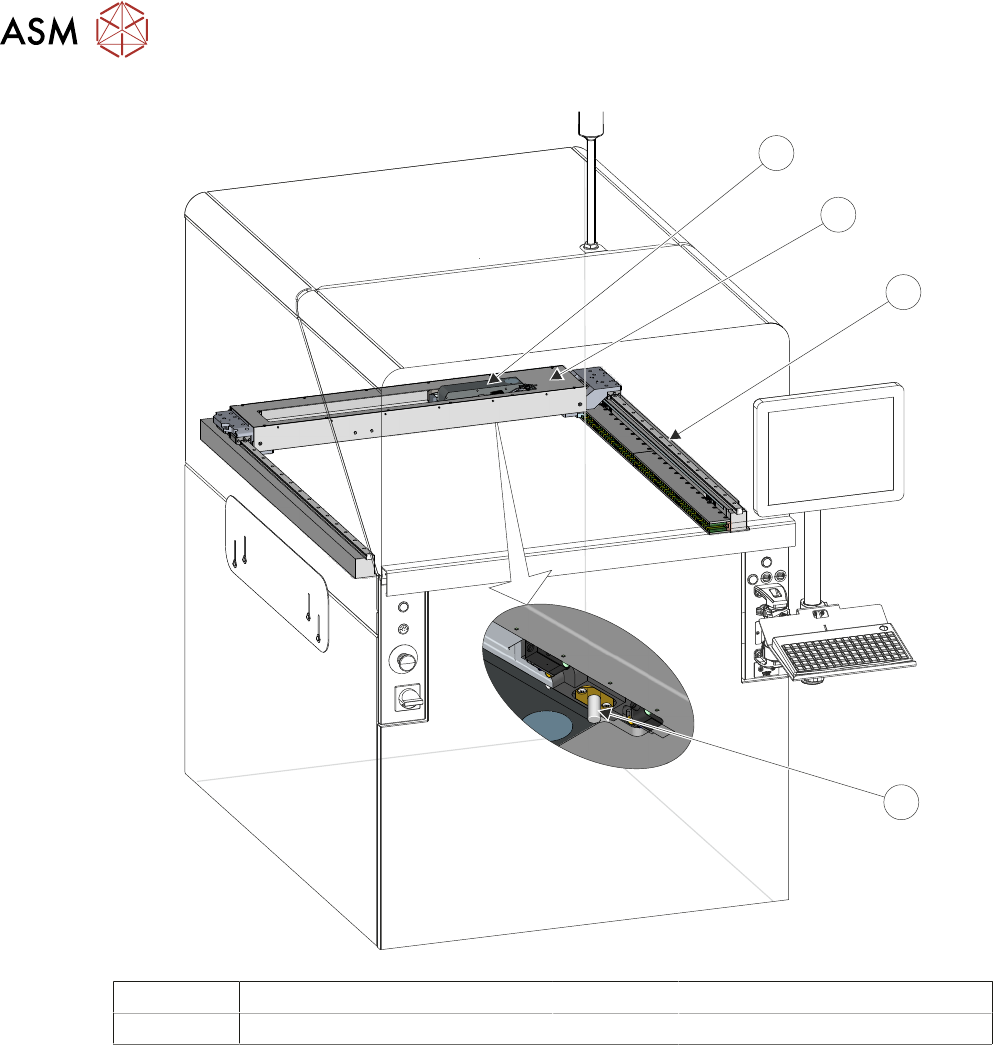
4.1.4.3 Paste Roll Height Laser
The paste roll height laser measures the height of the paste roll in front of the front squeegee dur-
ing a rearward print stroke.
4.1.4.4 Coplanarity Lasers
There are two coplanarity lasers mounted on the print carriage. During coplanarity calibration, the
lasers measure the difference between the top of the transport conveyors and the stencil in four po-
sitions.
4.1.4.5 Temperature and Humidity Sensors
The temperature and humidity sensors are mounted on the back of the print carriage, monitoring
the print area. The results are displayed on the HMI monitor.
4.1.5 Camera System Module
The camera system module is used for the following functions:
●
Use visual information to align the stencil to the product board
●
Use visual information for board or stencil inspection
●
Provide visual information for the user on the HMI monitor
●
Stops the board in the correct position for printing
The camera traverses in the X direction within the camera carriage using a linear motor. The cam-
era carriage traverses in the Y direction using a linear motor on the Y drive. The Y drive is also
shared by the under stencil cleaner.
4 MACHINE OVERVIEW
4.1 MODULE OVERVIEWS
36 TECHNICAL REFERENCE MANUAL DEK TQ 04/2021
4
3
2
1
1 Camera 3 Y Drive
2 Camera Carriage 4 Board Stop