88242361-04-01 Vol 1 DEK TQ TECHNICAL REFERENCE (1).pdfPDFA.pdf - 第86页
6 MACHINE CONTROL 6.4 EXTENDED POWER MODULE (EPM) 86 TECHNICAL REFERENCE MANUAL DEK TQ 04/2021 6.4.2 Servo Drive Card Servo drive cards are used to drive the following servo motors: ● Camera Y and X Drive ● Tooling Table…
6 MACHINE CONTROL
6.4 EXTENDED POWER MODULE (EPM)
TECHNICAL REFERENCE MANUAL DEK TQ 04/2021 85
EPM 2 Upper
Connector Description
J1-1 LH Auxiliary Conveyor Belt Motors
J1-2 RH Auxiliary Conveyor Belt Motors
J1-3 Centre Section Conveyor Belt Motors
J1-4 Front Squeegee Motor
J1-5 Power Input
J1-6 Alignment Actuator X
J1-7 Alignment Actuator Y Left
EPM 2 Lower
Connector Description
J1-1 Conveyor Width Motor (OTC Conveyors)
J1-2 Paste Dispenser Drive
J1-3 Solvent Dispense Arm Drive Motor
J1-4 Rear Squeegee Motor
J1-5 Power Input
J1-6 Fabric Roll Drive
J1-7 Alignment Actuator Y Right
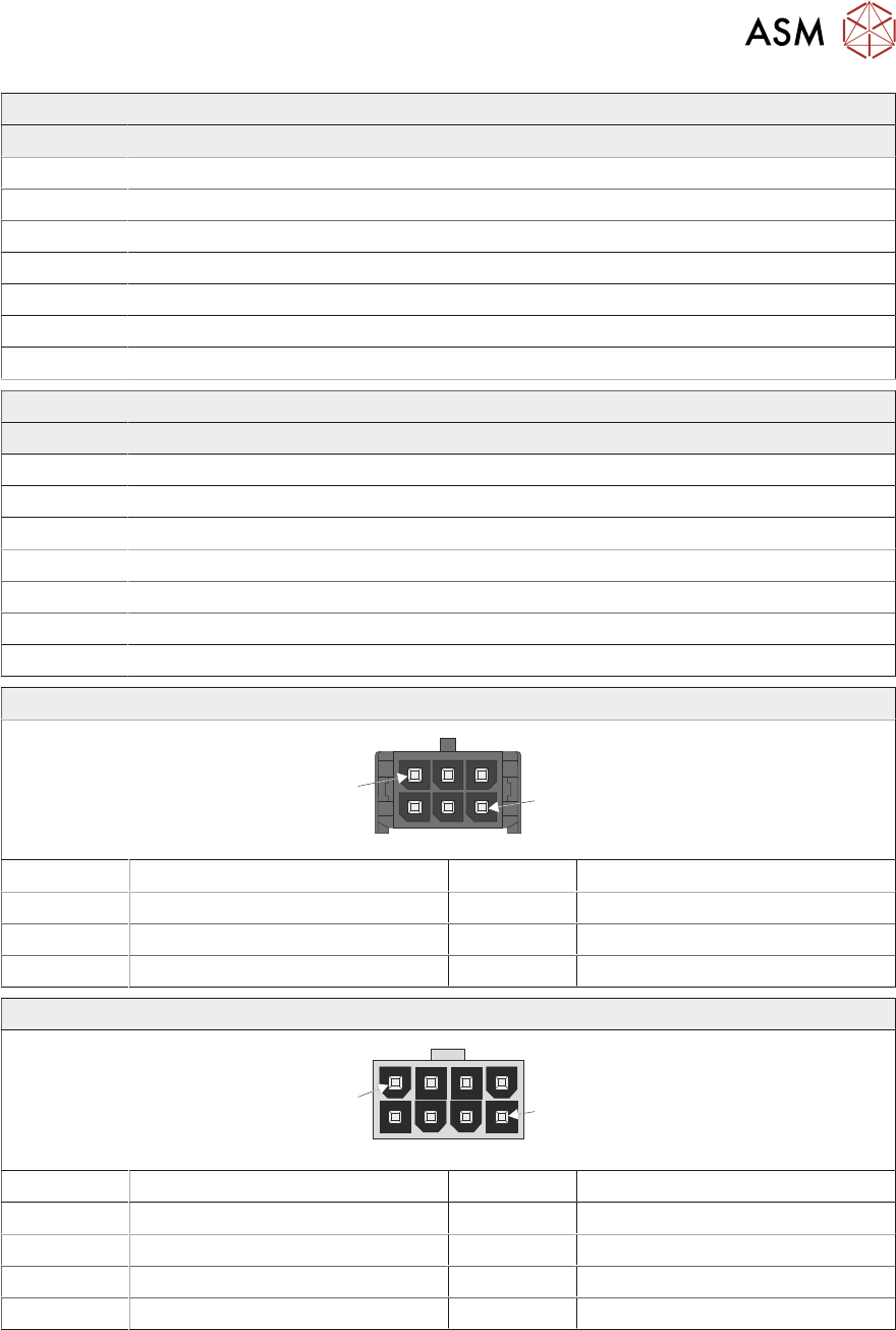
J*-1, J*-2, J*-3, J*-4, J*-6 and J*-7
1
6
Pin No Signal Pin No Signal
1 Not Used 4 Not Used
2 B+ 5 B-
3 A+ 6 A-
J*-5
1
8
Pin No Signal Pin No Signal
1 48V SW 5 48V SW
2 Not Used 6 Not Used
3 0V 7 24V US
4 0V 8 N/C
6 MACHINE CONTROL
6.4 EXTENDED POWER MODULE (EPM)
86 TECHNICAL REFERENCE MANUAL DEK TQ 04/2021
6.4.2 Servo Drive Card
Servo drive cards are used to drive the following servo motors:
●
Camera Y and X Drive
●
Tooling Table Lift
●
Conveyor Lift
●
Print Carriage Drive
●
Conveyor Width (APC Conveyors)
●
Under Stencil Cleaner
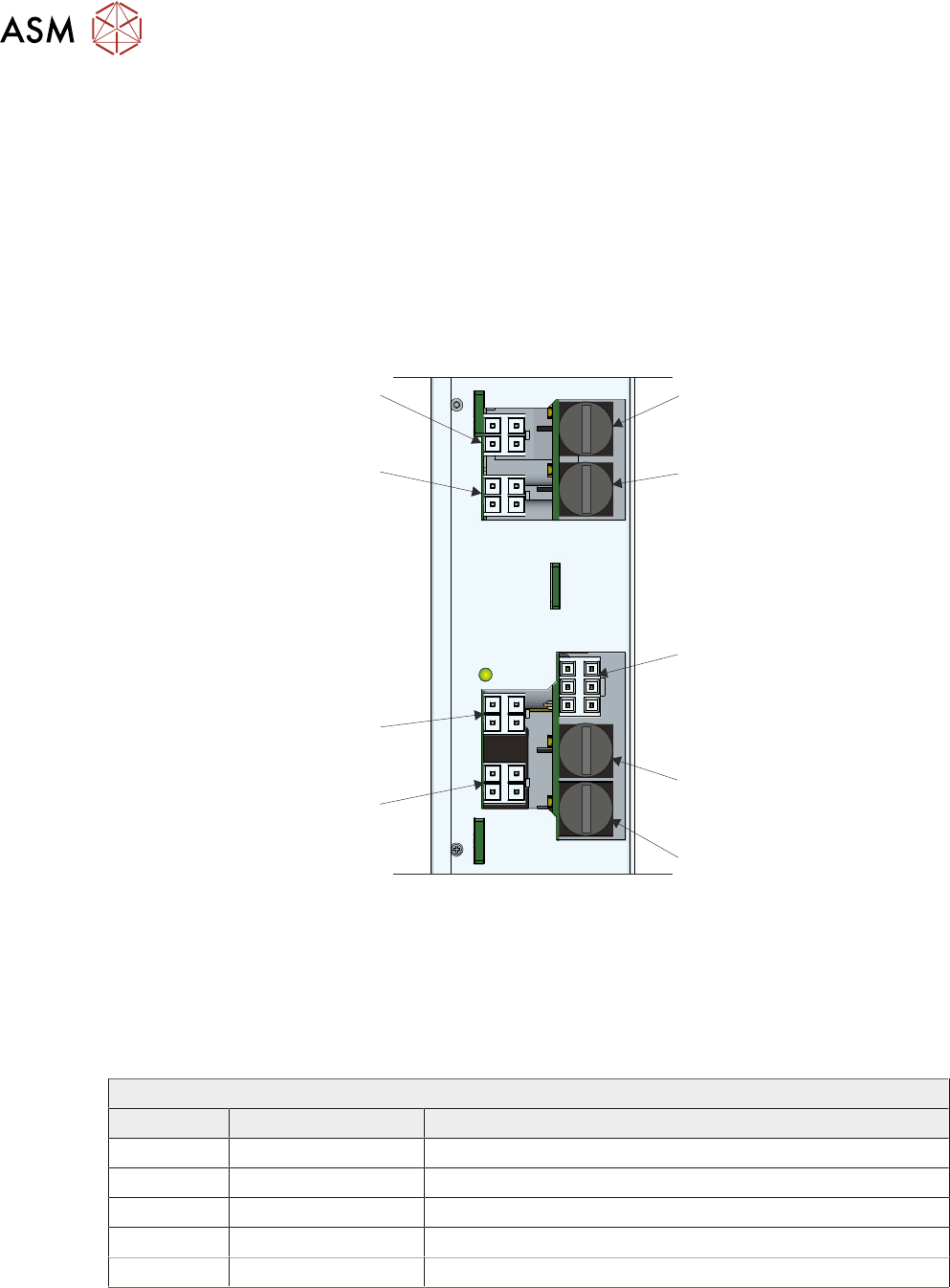
6.4.2.1 Connectors
J*-1
J*-2
J*-3
J*-4
J*-5
F*-3
F*-1
F*-4
F*-2
Servo Drive Card Connectors
NOTE
J* is either J1 if the drive card is in the upper position (top) or J2 if in the lower position (bottom) of
the EPM.
F* is either F1 if the drive card is in the upper position (top) or F2 if in the lower position (bottom) of
the EPM.
EPM 3 Upper
Connector Fuse Description
J1-1 F1-1 (2.5A) Tooling Table Lift
J1-2 F1-2 (2.5A) Conveyor Lift
J1-3 F1-3 (2A) Print Carriage Drive
J1-4 F1-4 (2A) Camera X Linear Drive
J1-5 Power Input
6 MACHINE CONTROL
6.4 EXTENDED POWER MODULE (EPM)
TECHNICAL REFERENCE MANUAL DEK TQ 04/2021 87
EPM 3 Lower
Connector Fuse Description
J2-1 F2-1 (5A) Camera Y Linear Drive
J2-2 F2-2 (2A) Under Stencil Cleaner Y Linear Drive
J2-3 F2-3 (2A) Conveyor Width Left Linear Drive (APC Conveyors)
J2-4 F2-4 (2A) Conveyor Width Right Linear Drive (APC Conveyors)
J2-5 Power Input
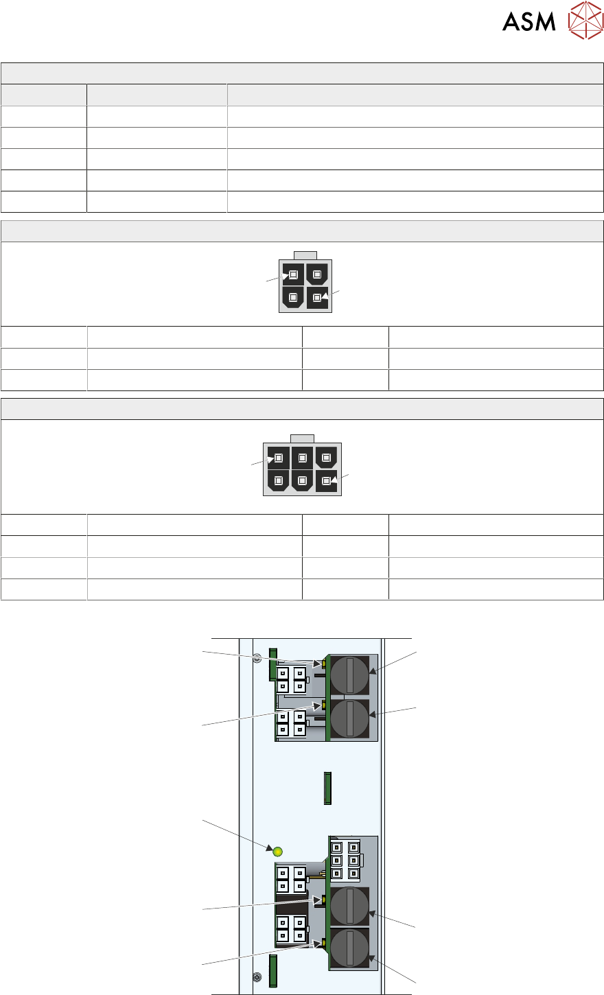
J*-1, J*-2, J*-3 and J*-4
1
4
Pin No Signal Pin No Signal
1 MTR Phase R 3 MTR Phase S
2 Earth 4 MTR Phase T
J*-5
1
6
Pin No Signal Pin No Signal
1 48V SW 4 48V SW
2 0V 5 0V
3 Not Used 6 24V US
6.4.2.2 LEDs
LED 1
LED 2
24V
Logic
LED 3
LED 4
F*-3
F*-1
F*-4
F*-2
Each output has its own fuse and indicator LED. If a fuse is blown, the LED is dimmed.