88242361-04-01 Vol 1 DEK TQ TECHNICAL REFERENCE (1).pdfPDFA.pdf - 第53页
5 POWER SUPPLY 5.2 POWER DISTRIBUTION TECHNICAL REFERENCE MANUAL DEK TQ 04/2021 53 5.2 POWER DISTRIBUTION Mains Input Power from the facility (110V to 230V ±10%, 50 to 60Hz A.C.) is routed to the Mains Isolator Switch at…

5 POWER SUPPLY
5.1 OVERVIEW
52 TECHNICAL REFERENCE MANUAL DEK TQ 04/2021
5.1.1.2 Rear
CB1
CB2
CB3
CB4
CB5
CB6
CB7
CB8
CB9
CB10
CB11
CB12
CB13
CB14
CB15
CB16
CB17
CB18
CB19
CB20
CB21
CB22
CB23
CB24
CB25
CB26
CB27
CB28
CB29
CB30
CB31
Circuit Breaker Current Rating Supply To Connector Circuit Breaker Function
CB1 3.15A M71SK15 Fans
CB2 3.15A M71SK01 Not Used
CB3 1.5A M71SK02 Not Used
CB4 3.15A M71SK02 Not Used
CB5 1.5A M71SK02 +24V US NuMotion Logic Supply
CB6 1.5A M71SK02 Not Used
CB7 1.5A M71SK03 Not Used
CB8 3.15A M71SK03 Not Used
CB9 3.15A M71SK03 Not Used
CB10 6.3A M71SK03 Not Used
CB11 3.15A M71SK04 +24V US ESIO-1
CB12 3.15A M71SK04 +24V SW ESIO-1
CB13 1.5A M71SK04 Not Used
CB14 3.15A M71SK05 +24V US ESIO-2
CB15 3.15A M71SK05 +24V SW ESIO-2
CB16 3.15A M71SK06 +24V US ESIO-3
CB17 3.15A M71SK06 +24V SW ESIO-3
CB18 3.15A M71SK07 +24V US ESIO-4
CB19 3.15A M71SK07 +24V SW ESIO-4
CB20 3.15A M71SK08 +24V US ESIO-5
CB21 3.15A M71SK08 +24V SW ESIO-5
CB22 1.5A M71SK08 Not Used
CB23 3.15A M71SK09 +24V US ESIO-6
CB24 3.15A M71SK09 +24V SW ESIO-6
CB25 3.15A M71SK10 Not Used
CB26 3.15A M71SK10 Not Used
CB27 3.15A M71SK11 Machine Lighting
CB28 3.15A M71SK11 Not Used
CB29 3.15A M71SK12 Not Used
CB30 1.5A M71SK13 Not Used
CB31 3.15A M71SK16 to M71SK 21 +24V US Drive Logic Power To
EPM’s

5 POWER SUPPLY
5.2 POWER DISTRIBUTION
TECHNICAL REFERENCE MANUAL DEK TQ 04/2021 53
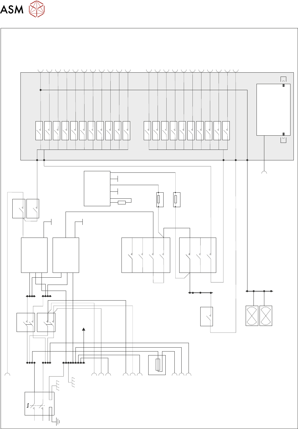
5.2 POWER DISTRIBUTION
Mains Input Power from the facility (110V to 230V ±10%, 50 to 60Hz A.C.) is routed to the Mains
Isolator Switch at the front of the machine. From the isolator, the supply is fed via an EMI line filter
and surge suppressor to the M71 Power Supply Enclosure, through a cable gland at the rear. In-
side the M71 Enclosure, the cores of the mains cable connect to the three terminal blocks: TB1
(Live), TB2 (Neutral) and TB3 (Earth/Ground). From the terminal blocks, mains power is distributed
to the following loads:
●
M71SK34 Temperature Control Unit (via CB2 on the front panel)
●
M71SK35 Internal Vacuum Pump (via CB2 on the front panel)
●
M71SK36 Display Monitor (via fuse M71F1 on the front panel)
●
24V DC PSU (via CB1 on the front panel)
●
48V DC PSU (via CB1 on the front panel)
The D.C. supplies from the PSU are fed to the power distribution PCB (some via the safety cir-
cuits), which mounts the enclosures rear connectors. Connected to this PCB is the PSU monitor
board, which provides a USB link to the P.C., allowing software to monitor the levels of D.C.
voltage present on the distribution PCB.
5 POWER SUPPLY
5.2 POWER DISTRIBUTION
54 TECHNICAL REFERENCE MANUAL DEK TQ 04/2021
TB2 TB5
TB3
TB6
TB8
24V US
24V US
24V SW
48V SW
Internal
Fans
M71SK34
M71SK35
M71F1
M71SK36
TB1 TB4
L
N
E
Mains Isolator
CB1
CB3
CB5
CB6
CB1
CB11
CB8
CB14
CB12
CB16
CB15
CB18
CB17
CB20
CB19
CB23
CB21
CB25
CB24
CB27
CB26
CB31
CB28
CB4
CB5
CB2
CON 1
CON 2
L
L
L
N
N
N
E
E
E
PSU 1
Dump
Circuit
PSU 2
L
N
E
L
N
E
0V0V
M71R1
M71F2
M71F3
1
1
5
5
15
16
42
50
51
3
3
7
2
2
6
6
4
4
8
0V
0V
+24V
+48V
M71SK43
M71SK02
M71SK02
M71SK30
(USB)
M71SK15
M71SK04
M71SK03
M71SK05
M71SK04
M71SK06
M71SK05
M71SK07
M71SK06
M71SK08
M71SK07
M71SK09
M71SK08
M71SK10
M71SK09
M71SK11
M71SK10
M71SK16 - 21
M71SK11
M71SK16 - 21
TB7
0V
PSU Monitor Board
M37PL28
M37PL29
Fuse
Power Distribution PCB
100mA T
246 5 3 1
500mA T