88242361-04-01 Vol 1 DEK TQ TECHNICAL REFERENCE (1).pdfPDFA.pdf - 第183页
10 STENCIL ALIGNMENT MODULE 10.4 CALIBRATIONS TECHNICAL REFERENCE MANUAL DEK TQ 04/2021 183 10.4.2 Coplanarity Coplanarity is achieved using calibrated tools, contact your local CSG office for more information.

10 STENCIL ALIGNMENT MODULE
10.4 CALIBRATIONS
182 TECHNICAL REFERENCE MANUAL DEK TQ 04/2021
10.4 CALIBRATIONS
10.4.1 Stencil Load Offset Position
The stencil load offset compensates for any tolerances of the print carriage position and/or the
stencil load paddle position which could result in the camera not looking at the stencil in correct
position in the Y axis.
NOTE
The camera reference position must be calibrated before the stencil load offset position can be set.
See Camera System Module chapter, Volume 2 for further details.
1. Select the Changeover tab.
2. Select Start Changeover.
3. Select Calibration29.Top.
4. Select Continue.
5. Select Continue.
6. From the drop-down menus select:
– Support – MagneticPinsNoVacuum
– Squeegees – Calibration Squeegee
– Stencil – Calibration29.Top
– Material – Calibration Material
7. Select Complete.
8. Select Menu.
9. Select Service.
10. Select Calibration.
11. Select Unload Stencil if a stencil is fitted.
12. Open the front cover.
13. Remove the stencil, if fitted.
14. Fit the calibration stencil 88241414 into the chase.
15. Close the front cover.
16. Press the System button.
17. Select Load Stencil.
18. Select Stencil Load Offset.
19. The stencil is reloaded and the camera finds the central stencil fiducial which is displayed in
the vision window.
20. If the fiducial has not been found, move the camera around by selecting inside the vision win-
dow to locate it.
21. Selecting Test Offset, reloads the stencil and moves the camera to the offset position.
22. Select Save and Exit.
23. Select Confirm.
24. Select Back.

10 STENCIL ALIGNMENT MODULE
10.4 CALIBRATIONS
TECHNICAL REFERENCE MANUAL DEK TQ 04/2021 183
10.4.2 Coplanarity
Coplanarity is achieved using calibrated tools, contact your local CSG office for more information.
10 STENCIL ALIGNMENT MODULE
10.5 REPLACEMENTS
184 TECHNICAL REFERENCE MANUAL DEK TQ 04/2021
10.5 REPLACEMENTS
10.5.1 Removal of Adaptor from Pneumatic Stencil Clamp
Adaptors are used to allow for thinner stencil frames to be fitted to the machine. To remove an ad-
aptor, carry out the following prcedure.
NOTE
The pneumatic stencil clamps are inflatable bladders and may become damaged due to age or
over pressure. As the cause would affect both clamps, the pneumatic stencil clamps must be
changed as a pair.
1. Select Shut Down.
2. Switch the mains isolator to OFF.
3. Remove the front panel.
4. Switch the Pneumatic Isolator to EXH.
5. Remove upper rear panel.
6. Remove right hand upper side panel.
7. Remove left hand upper side panel.
8. Open the front cover.
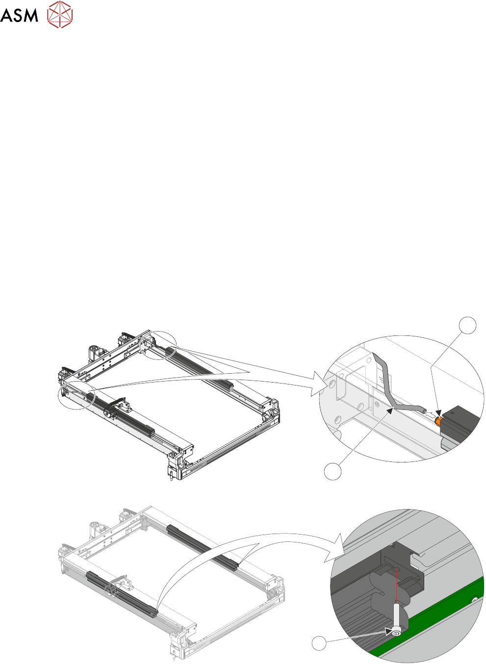
9. Disconnect the pneumatic tube (2) from the quick release fitting (1) located at the rear of the
pneumatic stencil clamp.
2
1
10. Using a 3mm Allen key, remove the securing screw (1) from the front of the adapter.
1