88242361-04-01 Vol 1 DEK TQ TECHNICAL REFERENCE (1).pdfPDFA.pdf - 第115页
7 PRINT CARRIAGE MODULE 7.1 OVERVIEW TECHNICAL REFERENCE MANUAL DEK TQ 04/2021 115 An extendible squeegee drip tray mechanism is incorporated into the carriage. For information on the squeegee drip tray, refer to 8 "…
7 PRINT CARRIAGE MODULE
7.1 OVERVIEW
114 TECHNICAL REFERENCE MANUAL DEK TQ 04/2021
1
3
5
2
4
4
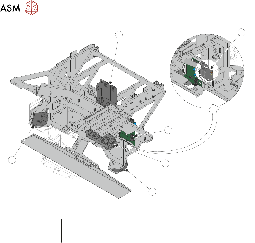
View on Rear Underneath
1 Stencil Presence Sensor 4 Auto Coplanarity Laser
2 Conditioning Board 5 Auto Coplanarity Laser Amplifiers
3 Stencil Loading Mechanism
The print carriage is a metal frame that is suspended from the top of the machine on four linear
bearings and is responsible for moving certain modules to their required positions in the Y direc-
tion. The carriage is driven by a ball screw connected to a servo motor via a drive belt. The print
carriage frame contains the following:
●
Squeegee Module - to transverse across the stencil in the Y direction (print stroke)
●
Stencil Loading Mechanism - to perform a stencil load
●
Coplanarity Lasers – to transport the auto coplanarity lasers and amplifiers to take measure-
ments from different positions
All positioning of the print carriage is referenced from the home position and calculated in the
machine software, taking into account:
●
Board width
●
Squeegee pitch
●
Hop over distance
●
Front and rear print limits
The print carriage homes during initialisation, which is carried out under the following circum-
stances:
●
At machine power up
●
After the application and recovery of the E Stop
●
When exiting machine diagnostics
7 PRINT CARRIAGE MODULE
7.1 OVERVIEW
TECHNICAL REFERENCE MANUAL DEK TQ 04/2021 115
An extendible squeegee drip tray mechanism is incorporated into the carriage. For information on
the squeegee drip tray, refer to 8
"SQUEEGEE MODULE" [}123].
For Information on the stencil loading mechanism, and stencil detection sensor, refer to 10 "STEN-
CIL ALIGNMENT MODULE" [}165].
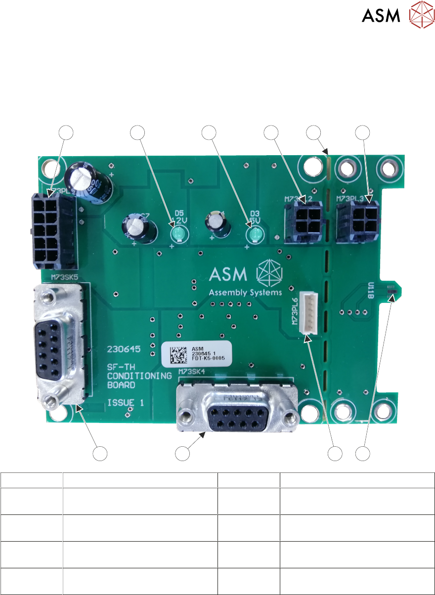
7.1.1 Conditioning Board
1 2 3
456
7
8 9
10
1 Extension Lead Connector 6 Squeegee Load Cell Connector
2 Extension Board Break-Off Point 7 Analogue I/O to ESIO Upper
Frame 3
3 Extension Lead Connector 8 Digital I/O to ESIO Breakout
Board Upper Frame 1A
4 Temperature & Humidity Sensor
(on the underside of the board)
9 12 Volt LED Indicator
5 Programming Connector
(Not Used)
10 5 Volt LED Indicator
The conditioning board is located at the rear of the print carriage. It features an on-board temperat-
ure and humidity sensor. The temperature and humidity is monitored in the print area and dis-
played to the operator on the screen.
A break-off section of the board can be separated from the main board, connected using an exten-
sion cable and positioned at the customers discretion.
The board is supplied with 24 volts to the Digital I/O connector. On-board regulators reduce the
voltage to 12V and 5V.
The conditioning board also contains the electronics for the squeegee strain gauge mechanism,
supplying software with feedback on squeegee pressure.
7 PRINT CARRIAGE MODULE
7.2 ELECTRICAL SCHEMATIC
116 TECHNICAL REFERENCE MANUAL DEK TQ 04/2021
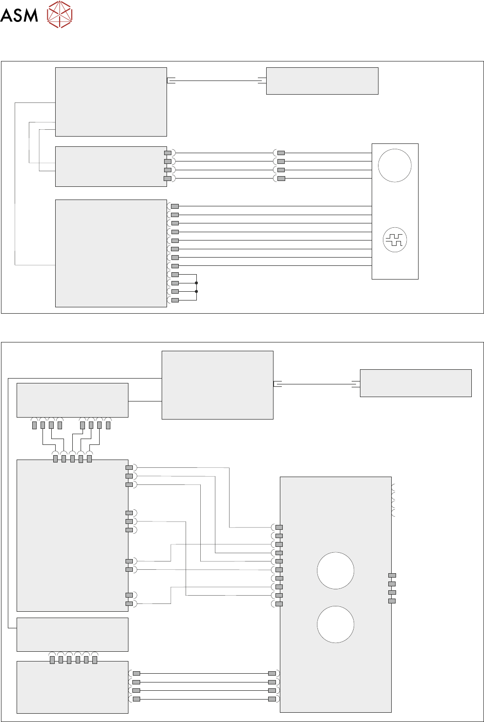
7.2 ELECTRICAL SCHEMATIC
Machine Controller
Controller Power Module
(CPM)
Fibre Optic Links
Ribbon Cables
SIO Link Cable
M
Print
Carriage
Drive Motor
MTR17
Extended Power Module
EPM3-1
J3
EPM3PL11
Print
Carriage
Encoder
4ENC3
ESIO-4
ENC3
7.2.1 Conditioning Board
Machine Controller
Controller Power Module
(CPM)
Fibre Optic Links
SIO Link
Cables
ESIO-5
ESIO-3
ESIO-3: Breakout A
ADC/DAC
Board 5
Conditioning Board
IO4 IO5
3ASK2
M73PL5
5PL3
M73SK1
3ASK23
3ASK24
3ASK13
3ASK14
M73SK4
M73PL2
Connector for
break-off
temperature and
humidity board
Connector for
squeegee load cell
°C
%RH