88242361-04-01 Vol 1 DEK TQ TECHNICAL REFERENCE (1).pdfPDFA.pdf - 第186页
10 STENCIL ALIGNMENT MODULE 10.5 REPLACEMENTS 186 TECHNICAL REFERENCE MANUAL DEK TQ 04/2021 13. Using a 3mm Allen key, loosen the M5 x20 cap head securing screw (1) from each side of the chase. 1 14. Remove the adapter (…
10 STENCIL ALIGNMENT MODULE
10.5 REPLACEMENTS
TECHNICAL REFERENCE MANUAL DEK TQ 04/2021 185
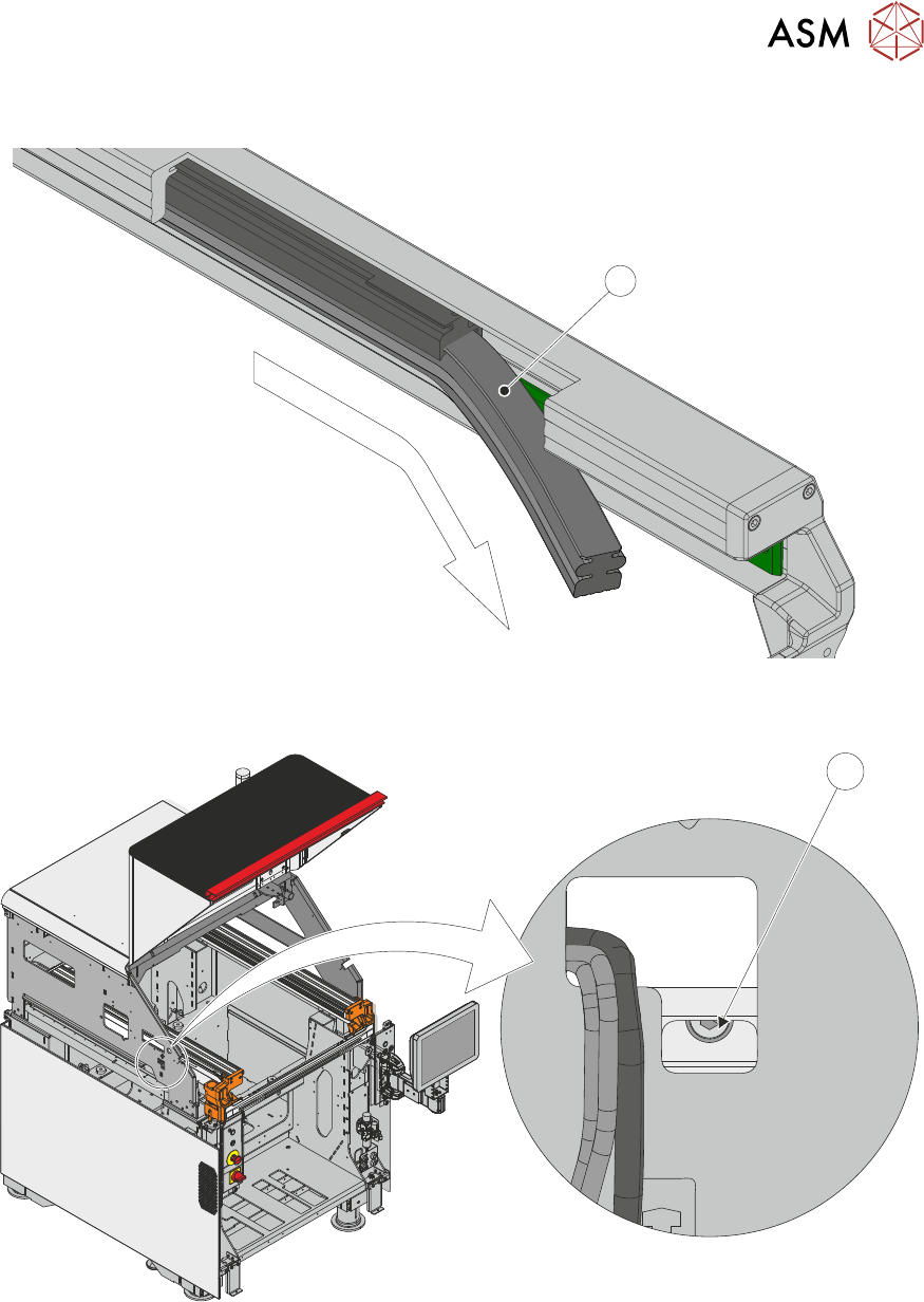
11. Slide the pneumatic stencil clamp (1) out of the front of the adapter.
1
12. To locate the left-hand stencil clamp securing screw (1), look through a cut-out in the left hand
side of the machine frame.
1
10 STENCIL ALIGNMENT MODULE
10.5 REPLACEMENTS
186 TECHNICAL REFERENCE MANUAL DEK TQ 04/2021
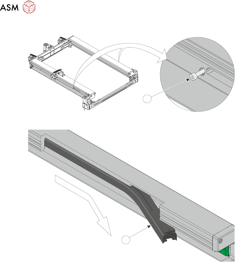
13. Using a 3mm Allen key, loosen the M5x20 cap head securing screw (1) from each side of the
chase.
1
14. Remove the adapter (1) from the extrusion by sliding it, towards the front of the machine, out
of the retaining slot, and flexing it downwards.
1
15. Ensure the chase inner extrusion is clean, and free from debris.
10 STENCIL ALIGNMENT MODULE
10.5 REPLACEMENTS
TECHNICAL REFERENCE MANUAL DEK TQ 04/2021 187
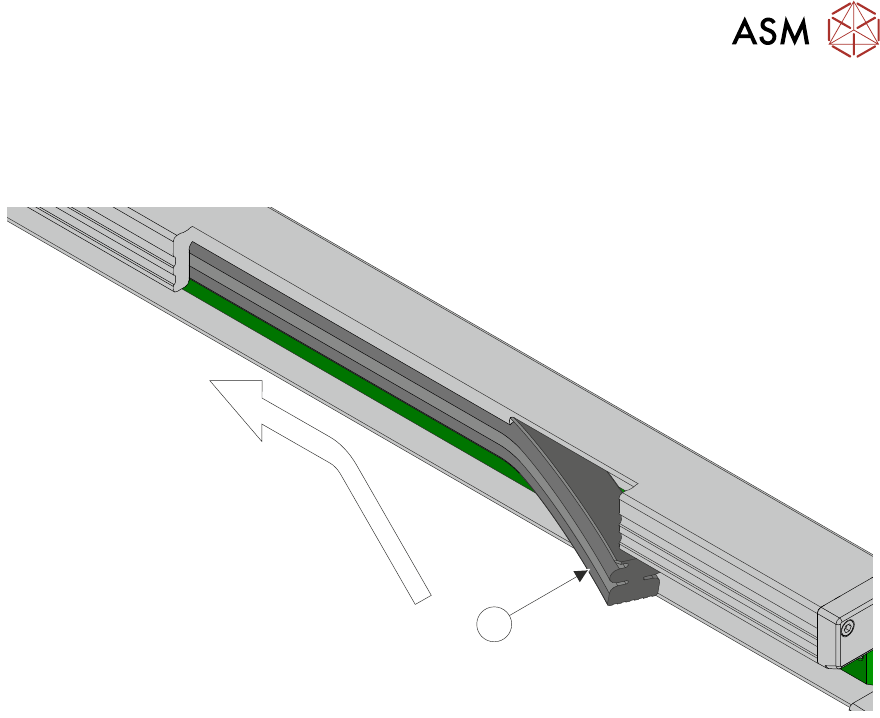
16. Slide the pneumatic stencil frame clamp (1) into the slot in the bottom of the chase inner ex-
trusion, with the pneumatic fitting to the rear.
NOTE
Ensure that the clamp is not pinched or folded as it is fitted into the chase inner extrusion.
1
17. Once the clamp is fully inserted, replace the chase securing screw (1).
18. Connect the pneumatic tube to the quick release fitting at the rear of the stencil clamp.
19. Switch the Pneumatic Isolator to SUP.
20. Replace the upper rear panel.
21. Replace the RH upper side panel.
22. Replace the LH upper side panel.
23. Replace the front panel.
24. Close the front cover.
25. Switch the mains isolator to ON.