88242361-04-01 Vol 1 DEK TQ TECHNICAL REFERENCE (1).pdfPDFA.pdf - 第67页
5 POWER SUPPLY 5.4 POWER MONITORING TECHNICAL REFERENCE MANUAL DEK TQ 04/2021 67 5.4 POWER MONITORING The PSU monitoring board is a stand-off PCB of the power distribution PCB in the power supply enclosure. 2 1 PSU'…
5 POWER SUPPLY
5.3 POWER SUPPLY ENCLOSURE
66 TECHNICAL REFERENCE MANUAL DEK TQ 04/2021
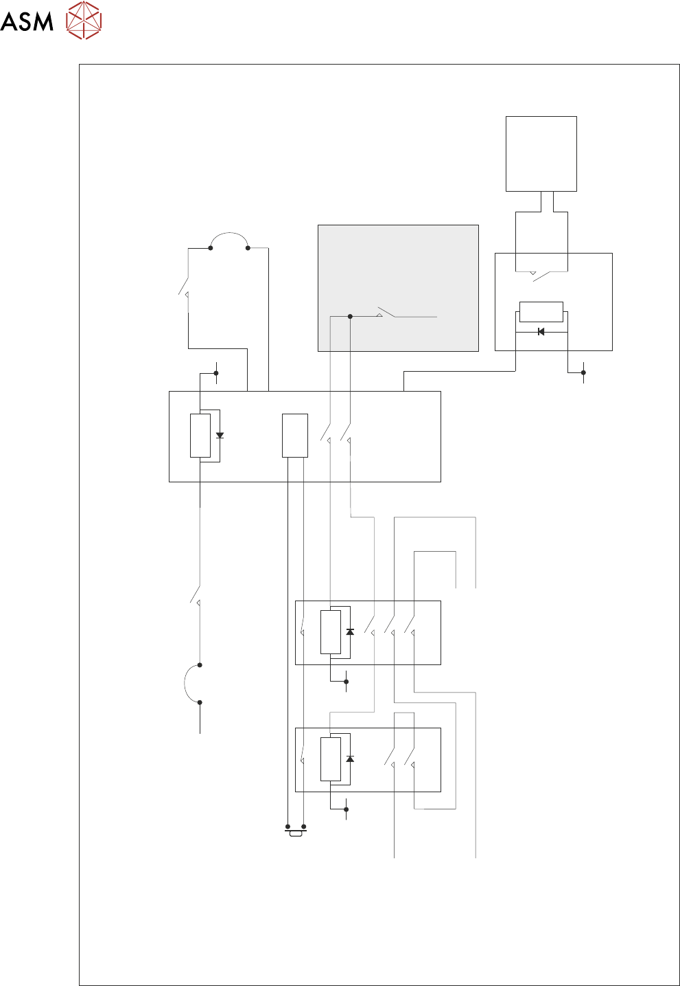
E Stop
Blanking Plug
E Stop
Button
Safety
Inputs
0V
0V
E Stop Supply
(from Machine
Control)
System Button
24V Supply
48V Supply
48V Out
24V SW
24V
Supply
CB4
Power
Distribution
PCB
Main
Cover Switch
Single Cover
Blanking Plug
E Stop
Relay
(RL 1)
Relay
(RL 2)
Con 1 Con 2
Reset
0V0V
PSU 2
Simplified Safety Circuit
5 POWER SUPPLY
5.4 POWER MONITORING
TECHNICAL REFERENCE MANUAL DEK TQ 04/2021 67
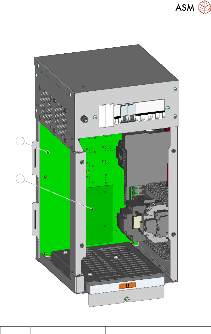
5.4 POWER MONITORING
The PSU monitoring board is a stand-off PCB of the power distribution PCB in the power supply
enclosure.
2
1
PSU's Removed For Clarity
1 Power Distribution PCB 2 PSU Monitor Board
5 POWER SUPPLY
5.4 POWER MONITORING
68 TECHNICAL REFERENCE MANUAL DEK TQ 04/2021
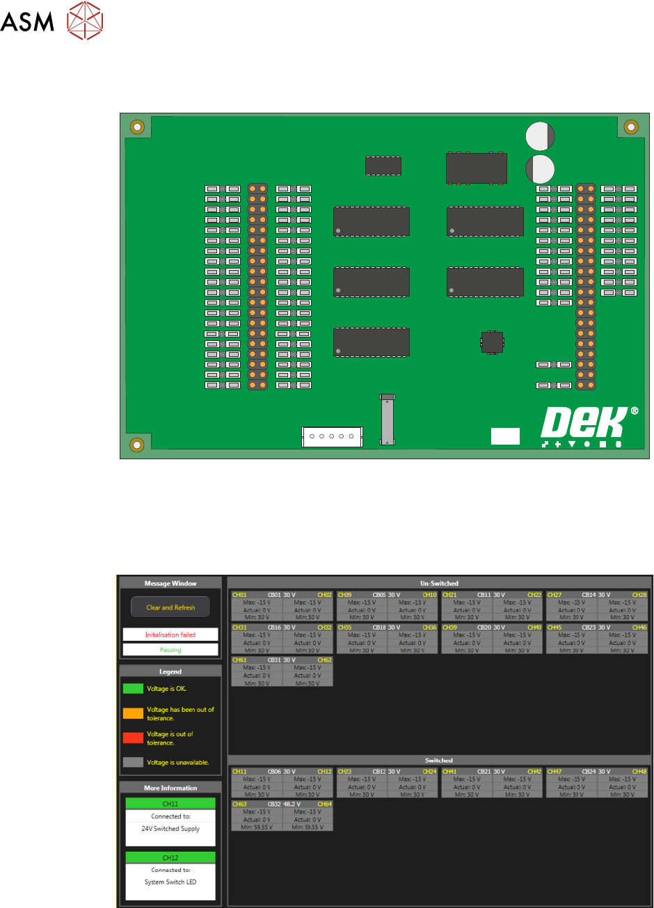
This board monitors the voltages at circuit breakers CB1 to CB31 on the power distribution PCB
and sends a data stream via the USB port (M71SK30) to the machine controller (PC).
PSU MONITOR BOARD
181507 ISSUE
To view the voltage readings on the machine monitor, carry out the following:
1. Switch ON and initialise the machine.
2. On the keyboard, press the Windows key to access the taskbar.
3. On the taskbar, select Start, Programs, DEK Power Monitor:
The displayed circuit breakers are split in two halves. The top half displays the un-switched
voltages (US) and the bottom half, the switched voltages (SW). If power monitoring is used during
an E Stop condition, all the SW circuit breakers are grey until the system button is pressed.