88242361-04-01 Vol 1 DEK TQ TECHNICAL REFERENCE (1).pdfPDFA.pdf - 第168页
10 STENCIL ALIGNMENT MODULE 10.1 OVERVIEW 168 TECHNICAL REFERENCE MANUAL DEK TQ 04/2021 Positioning of the stencil actuators is calculated in the machine software and referenced from the home position. The stencil actuat…
10 STENCIL ALIGNMENT MODULE
10.1 OVERVIEW
TECHNICAL REFERENCE MANUAL DEK TQ 04/2021 167
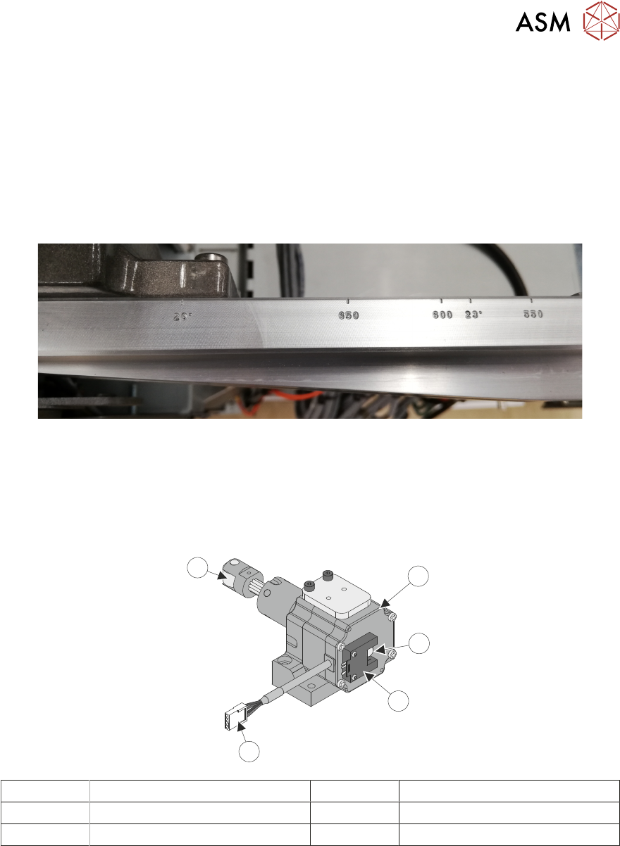
The chase width is adjustable and can be set to accommodate stencil sizes from 29” (736.6mm) to
550mm. The following most common sized stencils used are engraved on the front and rear of the
chase frame:
●
29” (736.6mm)
●
650mm
●
600mm
●
23” (584.2mm)
●
550mm
NOTE
To prevent a collision with the drip tray a short drip tray (360mm) should be used in conjunction
with a stencil size of 620mm (24.409") or less.
The stencil frame thickness is 25 to 40mm without the stencil clamp adapter.
10.1.2 Alignment Actuators
1
3
4
2
5
1 Alignment Actuator Motor 4 Electrical Connection
2 Alignment Actuator Plunger 5 Contact Roller
3 Home Sensor
The actuators are configured in a three-point contact arrangement and are controlled and driven in-
dependently to give maximum flexibility in stencil movement in the X, Y and Theta.
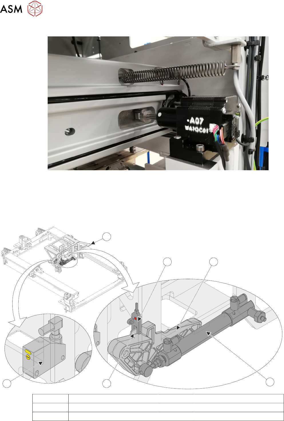
A spring fitted between the machine frame and the chase ensures that the chase is pulled against
the actuator rollers at all times.
10 STENCIL ALIGNMENT MODULE
10.1 OVERVIEW
168 TECHNICAL REFERENCE MANUAL DEK TQ 04/2021
Positioning of the stencil actuators is calculated in the machine software and referenced from the
home position. The stencil actuators only home during initialization, which can be from power-up or
exiting diagnostics. When homing, the stepper motor retracts the actuator plunger until the plunger
reaches the home sensor mounted on the rear of the motor.
10.1.3 Stencil Loading Mechanism
1
3
2
45
6
1 Paddle Home Sensor 4 Home Vane
2 Paddle 5 Stencil Presence Sensor
3 Paddle Cylinder 6 Print Carriage
10 STENCIL ALIGNMENT MODULE
10.1 OVERVIEW
TECHNICAL REFERENCE MANUAL DEK TQ 04/2021 169
A stencil is manually loaded into the machine by the operator and the stencil loading mechanism
accurately positions the stencil in the chase. It is incorporated into the print carriage, using a re-
tractable paddle to manoeuvre the stencil backwards and forwards to its correct position.
When Load Stencil is selected, the print carriage drives forward until the rear edge of the stencil is
located by the stencil presence sensor. The print carriage is then driven forwards until it clears the
inner face of the stencil frame. The stencil paddle is lowered, and the print carriage is reversed,
driving the stencil to the rear of the chase. Once in position, the paddle retracts and the print car-
riage drives back by the set ‘hop over distance’, passing over the stencil frame again, the paddle is
lowered and pushes the stencil forwards into the correct position. The paddle is retracted and the
stencil clamps are activated.
The stencil presence sensor, located on the inside of the print carriage, is a photoelectric diffuse
sensor, and has dual functionality. It is used to both confirm the presence of a stencil in the chase,
and to locate the edge of the stencil during the loading procedure.
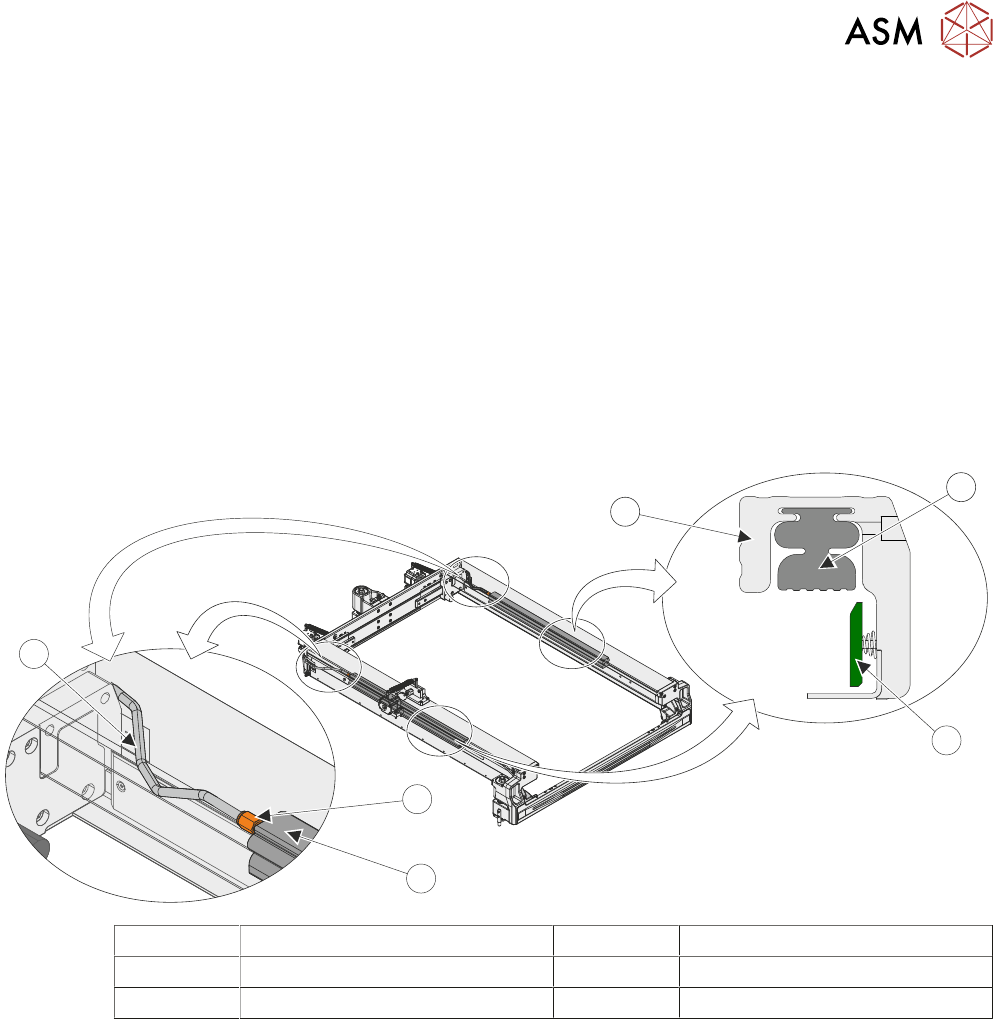
10.1.4 Stencil Clamps
3
1
4
2
2
5
1 Adjustable Stencil Holder 4 Pneumatic Quick Release Fitting
2 Pneumatic Stencil Clamp 5 Pneumatic Tube
3 Stencil Guide Strip
Once the stencil is in position, it is clamped using a pair of pneumatically operated stencil clamps.
The clamps are hollow rubber bladders and when pneumatic pressure is applied they expand
providing a downward force onto the stencil frame.