88242361-04-01 Vol 1 DEK TQ TECHNICAL REFERENCE (1).pdfPDFA.pdf - 第147页
9 PASTE DISPENSER SYSTEM 9.3 ADJUSTMENTS AND SETTINGS TECHNICAL REFERENCE MANUAL DEK TQ 04/2021 147 9.3.1.2 Electrical Setting Ensure that the measurement in 9.3.1.1 "Mechanical Setting" [ } 146] is correct be…
9 PASTE DISPENSER SYSTEM
9.3 ADJUSTMENTS AND SETTINGS
146 TECHNICAL REFERENCE MANUAL DEK TQ 04/2021
9.3 ADJUSTMENTS AND SETTINGS
9.3.1 Paste Level Sensor (Cartridge)
9.3.1.1 Mechanical Setting
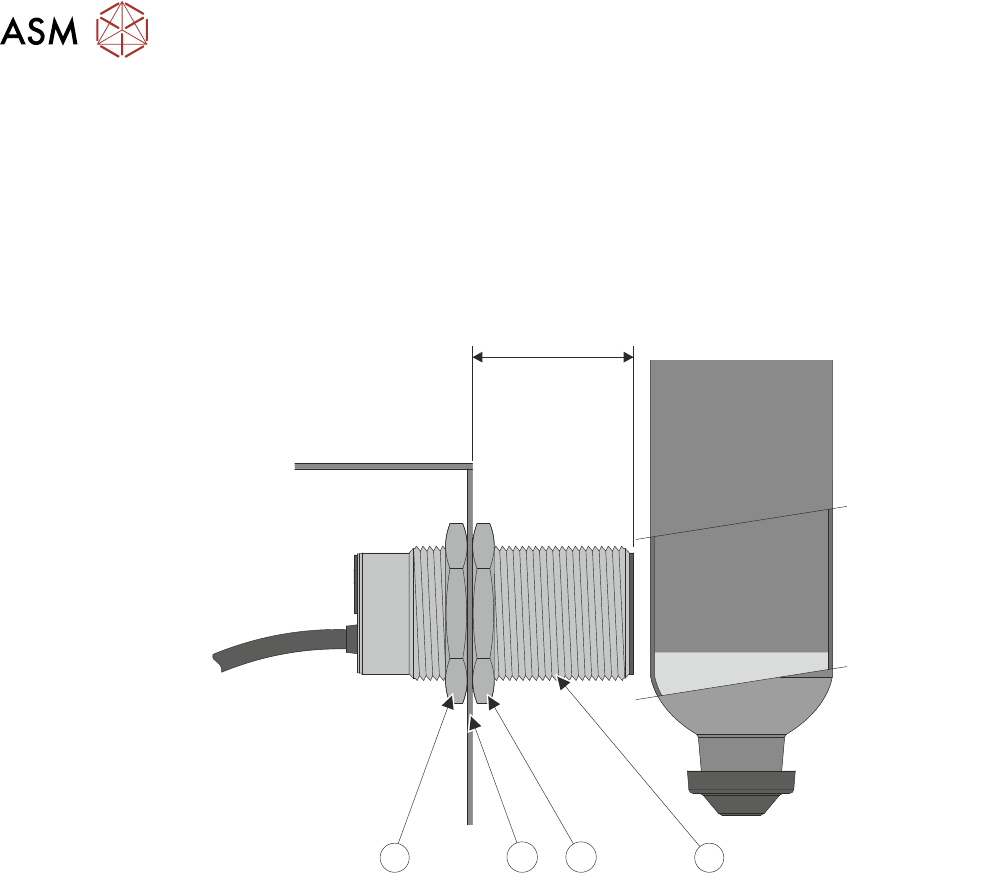
1. Open the front cover.
2. Check the 37mm measurement between the cartridge paste regulator assembly (3) and the
end of the paste level sensor (1) as shown below.
37mm
1
2
2
3
3. If adjustment is required, loosen the securing nuts (2) on the sensor (1), adjust the sensor to
achieve the 37mm
dimension from the cartridge paste regulator assembly (3) to the end of
the sensor (1). Tighten the securing nuts (2).
9 PASTE DISPENSER SYSTEM
9.3 ADJUSTMENTS AND SETTINGS
TECHNICAL REFERENCE MANUAL DEK TQ 04/2021 147
9.3.1.2 Electrical Setting
Ensure that the measurement in 9.3.1.1 "Mechanical Setting" [}146] is correct before adjusting the
sensitivity of the paste level sensor.
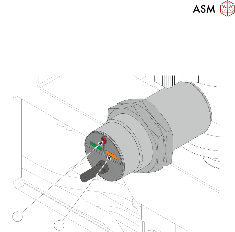
1. Fit an empty paste cartridge into the paste dispenser.
2. Slowly adjust the sensitivity control (2) to the point where the amber status LED (1) switches
ON
.
1
2
3. Fit a full paste cartridge into the paste dispenser. The amber status LED (1) switches OFF.
4. Slowly adjust the sensitivity control (2) anti clockwise to the point where the amber status LED
switches ON
. Note the amount of turns taken.
5. Turn the sensitivity control (2) clockwise half the noted amount of turns above. The amber
status LED (1) switches OFF
.
6. Remove and refit the full cartridge, ensuring the amber LED (1) switches on and off.
9.3.2 Paste Dispenser Regulator
For information on the regulator setting, refer to the Pneumatic Module chapter.
9 PASTE DISPENSER SYSTEM
9.3 ADJUSTMENTS AND SETTINGS
148 TECHNICAL REFERENCE MANUAL DEK TQ 04/2021
9.3.3 Paste Level Sensor (Jar)
9.3.3.1 Mechanical Setting
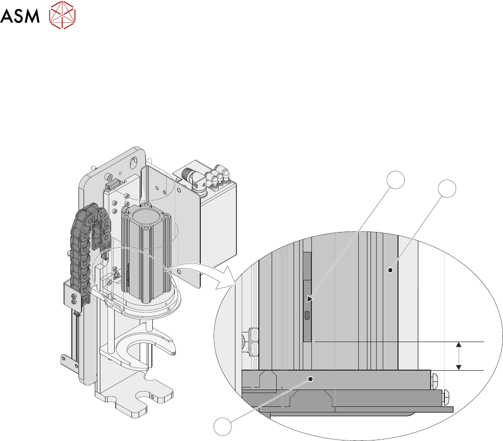
1. Open the front cover.
2. Check the 24mm measurement between the end of the paste jar low level reed switch (1) and
the top of the paste jar cylinder support plate (3). The reed switch is located in the paste jar
cylinder (2).
24mm
2
3
1