88242361-04-01 Vol 1 DEK TQ TECHNICAL REFERENCE (1).pdfPDFA.pdf - 第69页
5 POWER SUPPLY 5.4 POWER MONITORING TECHNICAL REFERENCE MANUAL DEK TQ 04/2021 69 Each circuit breaker has two channels, measuring the voltage before and after the circuit breaker. Each channel displays the minimum, maxim…
5 POWER SUPPLY
5.4 POWER MONITORING
68 TECHNICAL REFERENCE MANUAL DEK TQ 04/2021
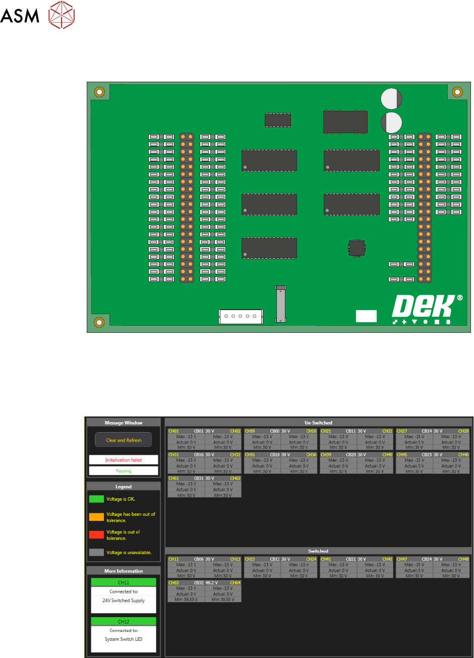
This board monitors the voltages at circuit breakers CB1 to CB31 on the power distribution PCB
and sends a data stream via the USB port (M71SK30) to the machine controller (PC).
PSU MONITOR BOARD
181507 ISSUE
To view the voltage readings on the machine monitor, carry out the following:
1. Switch ON and initialise the machine.
2. On the keyboard, press the Windows key to access the taskbar.
3. On the taskbar, select Start, Programs, DEK Power Monitor:
The displayed circuit breakers are split in two halves. The top half displays the un-switched
voltages (US) and the bottom half, the switched voltages (SW). If power monitoring is used during
an E Stop condition, all the SW circuit breakers are grey until the system button is pressed.

5 POWER SUPPLY
5.4 POWER MONITORING
TECHNICAL REFERENCE MANUAL DEK TQ 04/2021 69
Each circuit breaker has two channels, measuring the voltage before and after the circuit breaker.
Each channel displays the minimum, maximum and nominal voltages since the machine was last
powered up or Refresh Values was selected. The channel is displayed in red if the voltage is cur-
rently out of tolerance, amber if the voltage has previously been out of tolerance or green if the
voltage is and has stayed within tolerance.
Selecting a circuit breaker on the screen displays more information on that breaker in the bottom
left of the screen.

5 POWER SUPPLY
5.4 POWER MONITORING
70 TECHNICAL REFERENCE MANUAL DEK TQ 04/2021