88242361-04-01 Vol 1 DEK TQ TECHNICAL REFERENCE (1).pdfPDFA.pdf - 第182页
10 STENCIL ALIGNMENT MODULE 10.4 CALIBRATIONS 182 TECHNICAL REFERENCE MANUAL DEK TQ 04/2021 10.4 CALIBRATIONS 10.4.1 Stencil Load Offset Position The stencil load offset compensates for any tolerances of the print carria…
10 STENCIL ALIGNMENT MODULE
10.3 ADJUSTMENTS AND SETTINGS
TECHNICAL REFERENCE MANUAL DEK TQ 04/2021 181
15. Press the System button.
16. Toggle Stencil Detector to OFF.
17. Select Exit.
18. Select Accept.
1 2
3
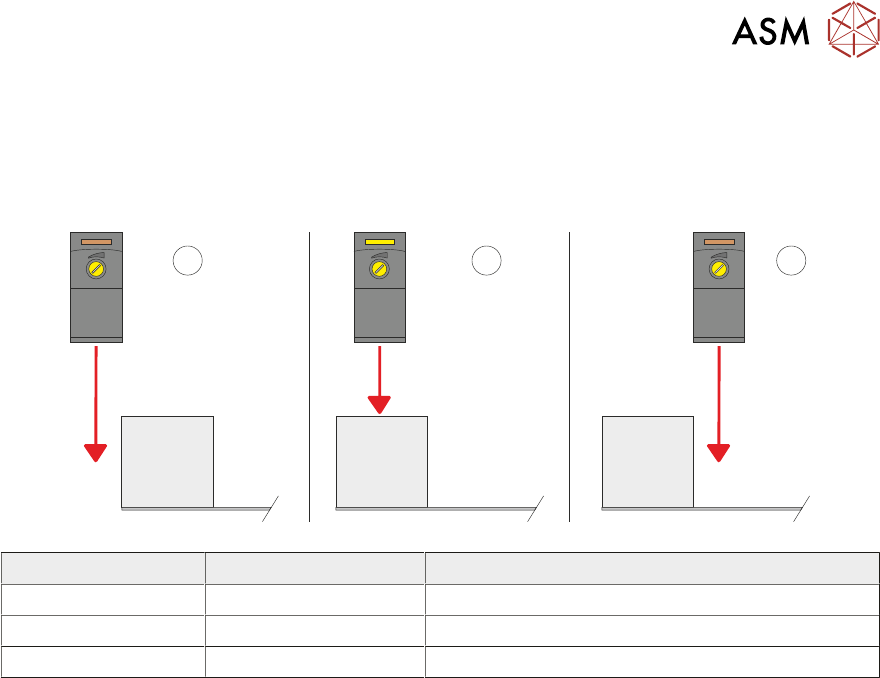
Item LED Sensor Position
1 Off Sensor behind the stencil
2 On Sensor over the stencil frame
3 Off Sensor over the stencil

10 STENCIL ALIGNMENT MODULE
10.4 CALIBRATIONS
182 TECHNICAL REFERENCE MANUAL DEK TQ 04/2021
10.4 CALIBRATIONS
10.4.1 Stencil Load Offset Position
The stencil load offset compensates for any tolerances of the print carriage position and/or the
stencil load paddle position which could result in the camera not looking at the stencil in correct
position in the Y axis.
NOTE
The camera reference position must be calibrated before the stencil load offset position can be set.
See Camera System Module chapter, Volume 2 for further details.
1. Select the Changeover tab.
2. Select Start Changeover.
3. Select Calibration29.Top.
4. Select Continue.
5. Select Continue.
6. From the drop-down menus select:
– Support – MagneticPinsNoVacuum
– Squeegees – Calibration Squeegee
– Stencil – Calibration29.Top
– Material – Calibration Material
7. Select Complete.
8. Select Menu.
9. Select Service.
10. Select Calibration.
11. Select Unload Stencil if a stencil is fitted.
12. Open the front cover.
13. Remove the stencil, if fitted.
14. Fit the calibration stencil 88241414 into the chase.
15. Close the front cover.
16. Press the System button.
17. Select Load Stencil.
18. Select Stencil Load Offset.
19. The stencil is reloaded and the camera finds the central stencil fiducial which is displayed in
the vision window.
20. If the fiducial has not been found, move the camera around by selecting inside the vision win-
dow to locate it.
21. Selecting Test Offset, reloads the stencil and moves the camera to the offset position.
22. Select Save and Exit.
23. Select Confirm.
24. Select Back.

10 STENCIL ALIGNMENT MODULE
10.4 CALIBRATIONS
TECHNICAL REFERENCE MANUAL DEK TQ 04/2021 183
10.4.2 Coplanarity
Coplanarity is achieved using calibrated tools, contact your local CSG office for more information.