88242361-04-01 Vol 1 DEK TQ TECHNICAL REFERENCE (1).pdfPDFA.pdf - 第24页
3 COVERS AND PANELS 3.1 OVERVIEW 24 TECHNICAL REFERENCE MANUAL DEK TQ 04/2021 8 7 6 5 4 3 2 1 View on Front – Dual Access Cover 1 Top Panel 5 Left Hand Lower Side Panel 2 Front Cover 6 Left Hand Safety Panel 3 Solvent Ta…
3 COVERS AND PANELS
3.1 OVERVIEW
TECHNICAL REFERENCE MANUAL DEK TQ 04/2021 23
3 COVERS AND PANELS
3.1 OVERVIEW
The definition throughout this manual is that a cover can be opened, and a panel requires tools to
remove.
In order to protect personnel and prevent damage, the following covers and panels are fitted to the
printer:
3.1.1 Front Cover
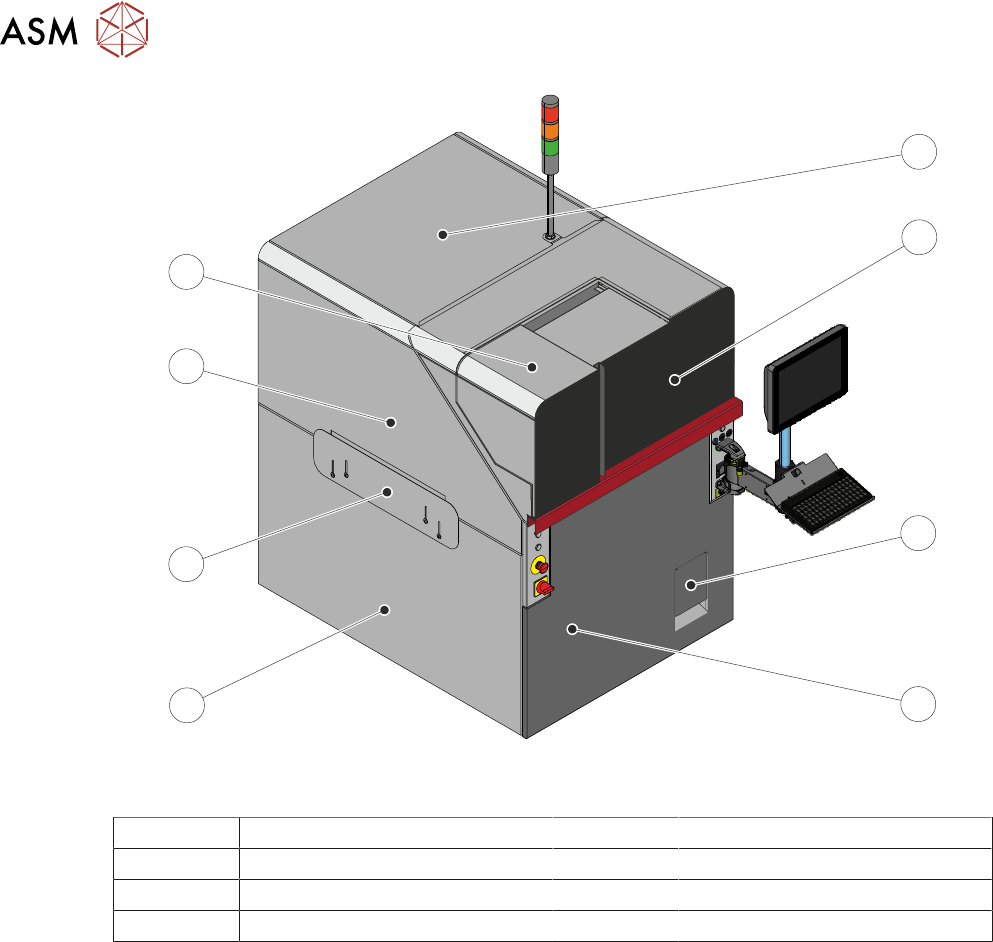
7
6
5
4
3
2
1
View on Front - Single Access Cover
1 Top Panel 5 Left Hand Lower Side Panel
2 Front Cover 6 Left Hand Safety Panel
3 Solvent Tank Cover 7 Left Hand Upper Side Panel
4 Front Panel
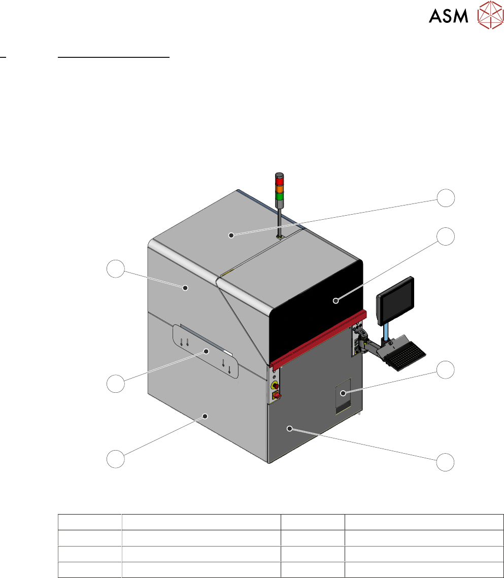
3 COVERS AND PANELS
3.1 OVERVIEW
24 TECHNICAL REFERENCE MANUAL DEK TQ 04/2021
8
7
6
5
4
3
2
1
View on Front – Dual Access Cover
1 Top Panel 5 Left Hand Lower Side Panel
2 Front Cover 6 Left Hand Safety Panel
3 Solvent Tank Cover 7 Left Hand Upper Side Panel
4 Front Panel 8 Paste Dispenser Cover
The front cover and the paste dispenser cover are fitted with safety switches to protect personnel.
Opening a cover when not permitted, creates an E Stop condition, stopping all movement within
the machine.
If the dual access cover is fitted the paste dispenser cover can be slid open (when the paste dis-
penser is at home) whilst the front cover remains closed allowing the machine to continue printing
during replenishment of the paste cartridge or jar.
As the front cover incorporates the paste dispenser cover lifting the front cover also lifts the paste
dispenser cover.
NOTE
The safety features designed into the printer are for the protection of all operators and maintenance
personnel. ASM strongly recommend safety devices are never overridden.
3 COVERS AND PANELS
3.2 PANEL REMOVAL
TECHNICAL REFERENCE MANUAL DEK TQ 04/2021 25
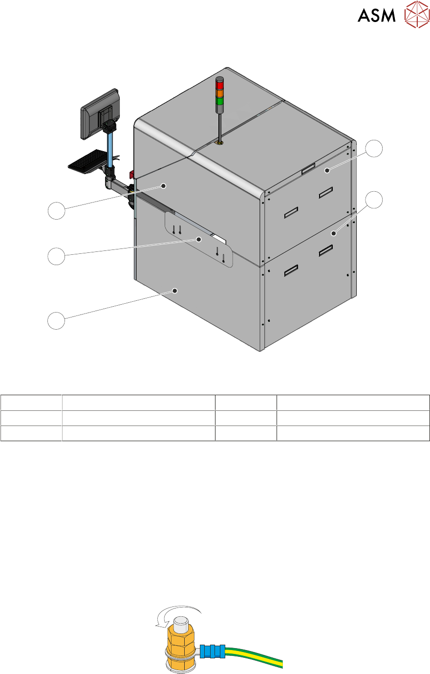
3.1.2 Rear Cover
5
4
3
2
1
View on Rear
1 Rear Upper Panel 4 Right Hand Safety Panel
2 Rear Lower Panel 5 Right Hand Top Side Panel
3 Right Hand Lower Side Panel
3.2 PANEL REMOVAL
NOTE
When refitting the panels, ensure that they are fitted correctly and securely.
3.2.1 Earth Bonding
The opening covers and the safety panels are mechanically bonded to the machine earth point.
The machine panels are electrically bonded using an earth stud on the panel connected to a green
and yellow insulated cable. Occasionally an earth cable must be removed so that the panel may be
moved away from the machine to gain more access.
Using an 8mm spanner, remove the two earth cable securing nuts and washer to detach the earth
cable from the panel.
Refit the washer and two nuts on to the earth stud for safe keeping.
When refitting the cable, ensure they are secured (tightly) onto a clean surface.