88242361-04-01 Vol 1 DEK TQ TECHNICAL REFERENCE (1).pdfPDFA.pdf - 第23页
3 COVERS AND PANELS 3.1 OVERVIEW TECHNICAL REFERENCE MANUAL DEK TQ 04/2021 23 3 COVERS AND PANELS 3.1 OVERVIEW The definition throughout this manual is that a cover can be opened, and a panel requires tools to remove. In…
2 SAFETY FEATURES
2.5 SAFETY LOCKOUT
22 TECHNICAL REFERENCE MANUAL DEK TQ 04/2021
2.5.2 Pneumatic Lockout
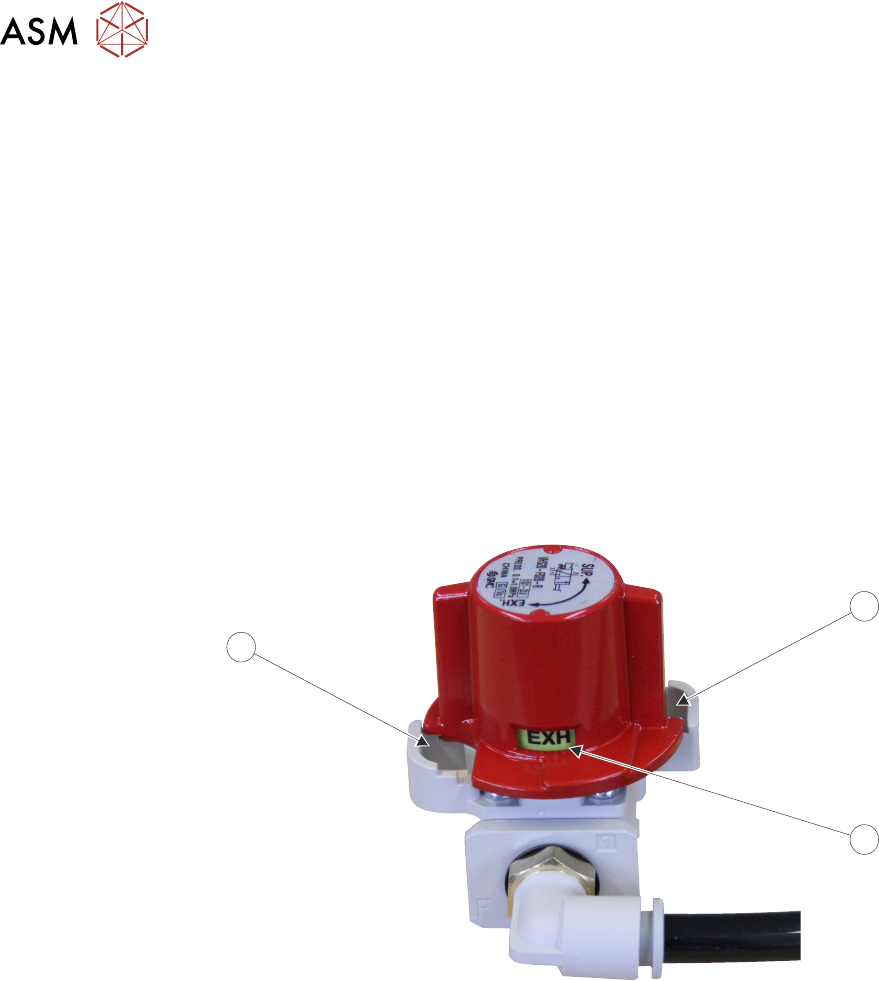
Pneumatic lockout of the printer is achieved by applying a padlock, or any other suitable locking
device to the pneumatic air switch. This can only be achieved when the switch is in the EXH
(Off)
position.
The pneumatic lockout switch is connected to the main air regulator at the front right hand side of
the machine, behind the front panel.
The switch positions are:
●
SUP (Supply) - On, air supply is fed to the printer
●
EXH (Exhaust) - Off, air supply is disconnected from the printer and the remaining pressure,
after the switch, is exhausted relieving the air pressure
To pneumatically lockout the printer, carry out the following procedure:
1. Ensure that electrical lockout has been completed.
2. Open the front cover.
3. Remove the front panel.
4. Turn the pneumatic switch (2) to the EXH position.
1
2
1
5. Fit a padlock or suitable locking device through the lockout hole (1).
This prevents the pneumatic switch being turned to the SUP position and completes the pneumatic
lockout.
3 COVERS AND PANELS
3.1 OVERVIEW
TECHNICAL REFERENCE MANUAL DEK TQ 04/2021 23
3 COVERS AND PANELS
3.1 OVERVIEW
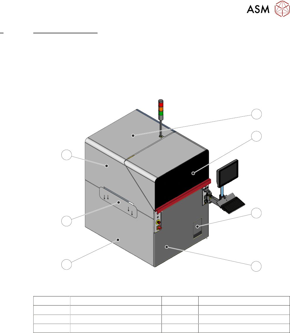
The definition throughout this manual is that a cover can be opened, and a panel requires tools to
remove.
In order to protect personnel and prevent damage, the following covers and panels are fitted to the
printer:
3.1.1 Front Cover
7
6
5
4
3
2
1
View on Front - Single Access Cover
1 Top Panel 5 Left Hand Lower Side Panel
2 Front Cover 6 Left Hand Safety Panel
3 Solvent Tank Cover 7 Left Hand Upper Side Panel
4 Front Panel
3 COVERS AND PANELS
3.1 OVERVIEW
24 TECHNICAL REFERENCE MANUAL DEK TQ 04/2021
8
7
6
5
4
3
2
1
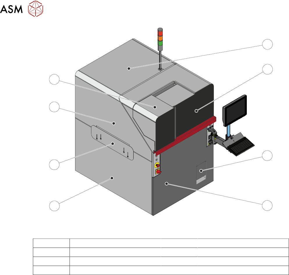
View on Front – Dual Access Cover
1 Top Panel 5 Left Hand Lower Side Panel
2 Front Cover 6 Left Hand Safety Panel
3 Solvent Tank Cover 7 Left Hand Upper Side Panel
4 Front Panel 8 Paste Dispenser Cover
The front cover and the paste dispenser cover are fitted with safety switches to protect personnel.
Opening a cover when not permitted, creates an E Stop condition, stopping all movement within
the machine.
If the dual access cover is fitted the paste dispenser cover can be slid open (when the paste dis-
penser is at home) whilst the front cover remains closed allowing the machine to continue printing
during replenishment of the paste cartridge or jar.
As the front cover incorporates the paste dispenser cover lifting the front cover also lifts the paste
dispenser cover.
NOTE
The safety features designed into the printer are for the protection of all operators and maintenance
personnel. ASM strongly recommend safety devices are never overridden.