88242361-04-01 Vol 1 DEK TQ TECHNICAL REFERENCE (1).pdfPDFA.pdf - 第161页
9 PASTE DISPENSER SYSTEM 9.4 REPLACEMENT PROCEDURES TECHNICAL REFERENCE MANUAL DEK TQ 04/2021 161 28. Fit the cartridge dispenser assembly by locating (4) the cartridge dispenser assembly (1) on the retaining dowels (2) …
9 PASTE DISPENSER SYSTEM
9.4 REPLACEMENT PROCEDURES
160 TECHNICAL REFERENCE MANUAL DEK TQ 04/2021
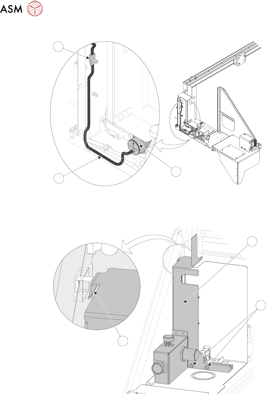
23. Place the cartridge paste regulator assembly (1) in position on the machine.
3
2
1
24. Feed the low paste sensor cable (3) through the cartridge bracket guard.
25. Connect the cartridge paste low level sensor's electrical connector (4).
26. Locate the retaining clip (3) of the cartridge paste regulator assembly (1) in the aperture in the
machines side plate.
3
2
1
27. Using a 4mm Allen key secure the cartridge paste regulator assembly in place with two M5
socket cap-head screws (2).
9 PASTE DISPENSER SYSTEM
9.4 REPLACEMENT PROCEDURES
TECHNICAL REFERENCE MANUAL DEK TQ 04/2021 161
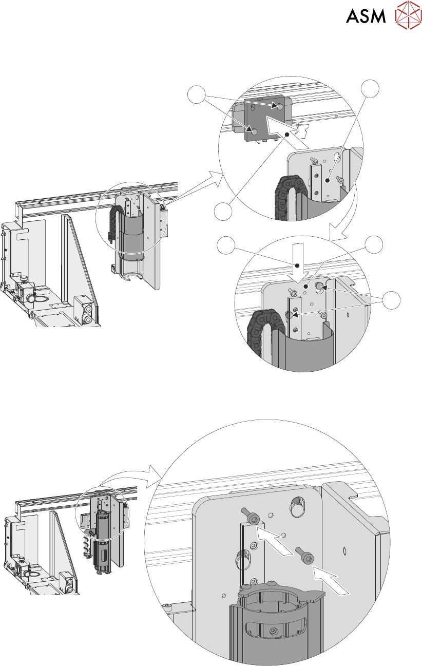
28. Fit the cartridge dispenser assembly by locating (4) the cartridge dispenser assembly (1) on
the retaining dowels (2) and pushing down (3).
4
2
1
3
2
1
29. Using a 4mm Allen key secure the assembly in place by tightening the two captive M5 socket
cap-head screws.
9 PASTE DISPENSER SYSTEM
9.4 REPLACEMENT PROCEDURES
162 TECHNICAL REFERENCE MANUAL DEK TQ 04/2021
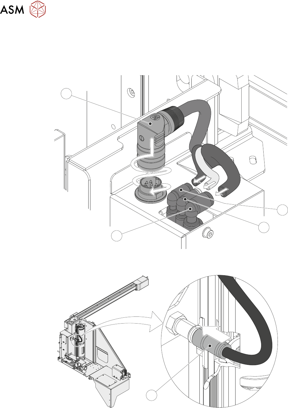
30. Connect the three pneumatic connectors (1-3) and the electrical connector (4) by locating it in
position and pushing down whilst tightening it up.
– Reconnect the down feed pneumatic tube (1) - 4mm tube labelled 1.
– Reconnect the up feed pneumatic tube (2) - 4mm tube labelled 2.
– Reconnect the paste pressure feed pneumatic tub (3) - 6mm tube.
4
3
2
1
31. Connect the paste cartridges cap pneumatic quick release connector (1) to the paste dis-
penser.
1
32. Fit the paste cartridge and cap into the paste dispenser.
33. Fit the stencil drip tray.
34. Fit the stencil.