Printer 710_810 v8 Transportation.pdf - 第13页
TRANS PORTATION MINOR RELO CATION Chapter Issue 7 Oct 06 Technical Reference Manual 34.13 13. Lock of f all five mounting feet using the l ocknuts. 14. Recheck the machine is level. 15. Recheck the machine hei ght has no…
TRANSPORTATION
MINOR RELOCATION
34.12 Technical Reference Manual Chapter Issue 7 Oct 06
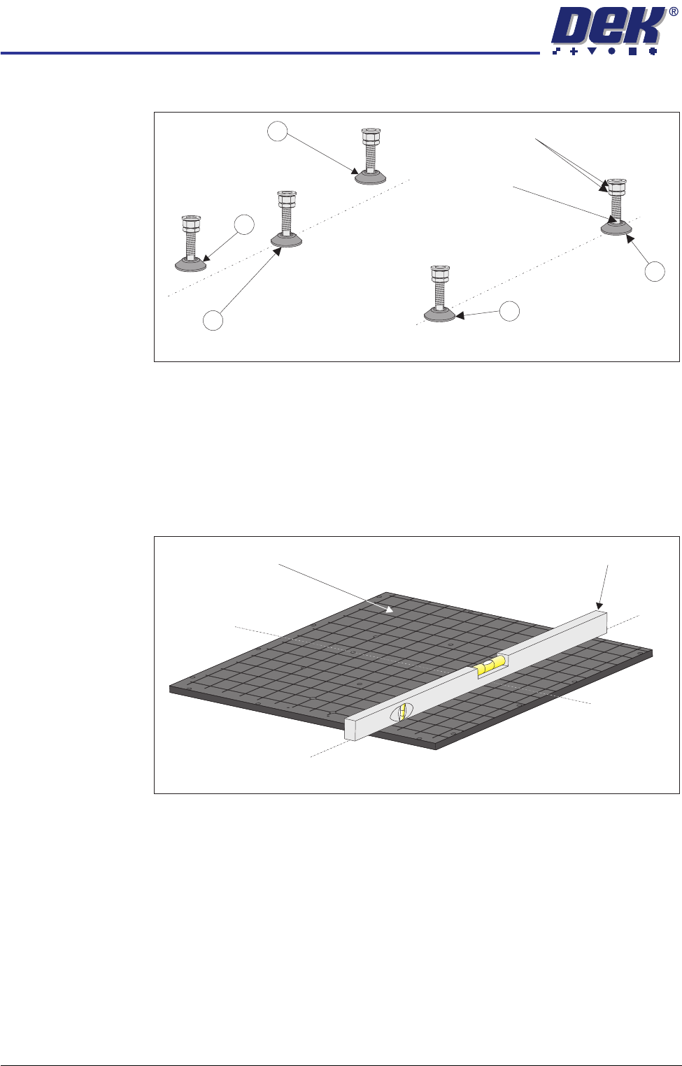
1. Adjust the front right hand foot (1) to achieve the desired height.
2. Adjust the front left hand foot (2) to approximately the same height.
3. Lower the rear centre mounting foot (3) so that it is in contact with the floor.
4. Raise the rear left (4) and rear right (5) mounting feet so they are not in
contact with the floor/leg spacers and the machine is supported on the front
two and rear centre mounting feet.
5. Place an engineering level on top of the manual tooling plate along the front
row of screws running from left to right.
6. Adjust the front left (2) mounting foot to level the machine in the X direction.
7. Move the engineering level along the centre row of screws running from front
to back.
8. Adjust the rear centre (3) mounting foot to level the machine in the Y
direction.
9. Repeat Steps 5 to 8 until the machine is level in both directions.
10. Carefully lower the rear left mounting foot (4) so that it is in contact with the
floor/leg spacer. Check the machine level has not been disturbed.
11. Carefully lower the rear right mounting foot (5) so that it is in contact with the
floor/leg spacer. Check the machine level has not been disturbed.
12. Raise the rear centre mounting foot (3) so it is not in contact with the floor.
Isometric View on Machine Mounting Feet
Locking Nuts
Front
4
3
2
1
Leg Adjuster
5
Engineering Level
Manual Tooling Plate
Isometric View on Manual Tooling Plate
Front
C
L
of Screws
C
L
of Screws
(Y direction)
(X direction)

TRANSPORTATION
MINOR RELOCATION
Chapter Issue 7 Oct 06 Technical Reference Manual 34.13
13. Lock off all five mounting feet using the locknuts.
14. Recheck the machine is level.
15. Recheck the machine height has not been disturbed.
16. Remove the engineering level from the machine.
On completion of relocation, carry out the following:
1. Reconnect electrical power supplies.
2. Reconnect pneumatic supplies.

TRANSPORTATION
MAJOR RELOCATION
34.14 Technical Reference Manual Chapter Issue 7 Oct 06
MAJOR RELOCATION
This procedure is to be utilized when the machine is being relocated on the
following occasions:
• Machine relocation to another site outside the original factory.
• If the machine has to experience any substantive shocks or vibration.
Machine
Preparation
Prior to a major relocation it is recommended the following is carried out:
• Machine capability check (see Machine Performance).
• Check the shock watches are in position (Shock Watch Locations figure
refers) and untriggered (indicator shows red when triggered). Replace any
triggered shock watches.
Prior to installing transit brackets to the machine ensure the following:
1. With power applied to the machine:
a. Home the moving rail.
b. Home the screen actuators.
c. Home the paste dispenser (if fitted).
2. Switch off and disconnect the electrical power.
3. Disconnect the air supply.
4. Remove/open the rear printhead cover.
5. On sliding cover machines remove the two upper side panels as detailed in
the Covers chapter.