Printer 710_810 v8 Transportation.pdf - 第45页
TRANS PORTATION MAJOR RELO CATION Chapter Issue 7 Oct 06 Technical Reference Manual 34.45 8. Replace t he studs wi th four mounting feet. NOTE For machines wi th the anti- vibrati on mounting feet opt ion, four anti -vib…
TRANSPORTATION
MAJOR RELOCATION
34.44 Technical Reference Manual Chapter Issue 7 Oct 06
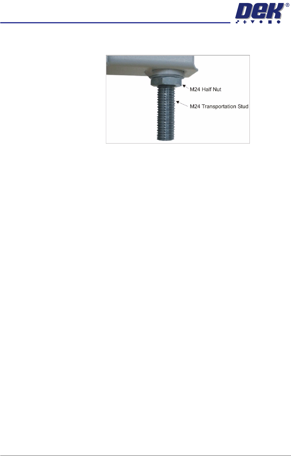
3. Replace the four corner mounting feet with four transportation studs, ensur-
ing that the shortest length of exposed thread, screws into the machine.
4. Place the machine on the base of the transportation box.
5. Relocate the forks under the base of the transportation box.
6. Raise the forks to gain access to the underside of the base of the transpor-
tation box.
7. Fit the four washers and nuts to secure the machine to the base of the
transportation box.
8. Lower and remove the forks.
9. Secure the sides and top of the transportation box with screws.
10. Wrap the loose items and pack separately. The machine is now ready for
transportation.
Unpacking 1. Unscrew the transportation box securing screws and remove the lid and
sides of the delivery crate.
2. Using the fork lift truck, locate the forks under the base of the transportation
box.
3. Raise the forks to gain access to the underside of the base of the transpor-
tation box.
4. Remove the four nuts and washers securing the machine to the base of the
transportation box using a 36mm spanner (wrench).
5. Lower the forks and relocate the forks under the machine base (preferably
from the rear so the weight of the machine is taken evenly on the front and
rear cross members).
6. Raise the forks, separating the machine from the base of the transportation
box.
7. Remove the four studs that secured the machine to the base of the trans-
portation box.
TRANSPORTATION
MAJOR RELOCATION
Chapter Issue 7 Oct 06 Technical Reference Manual 34.45
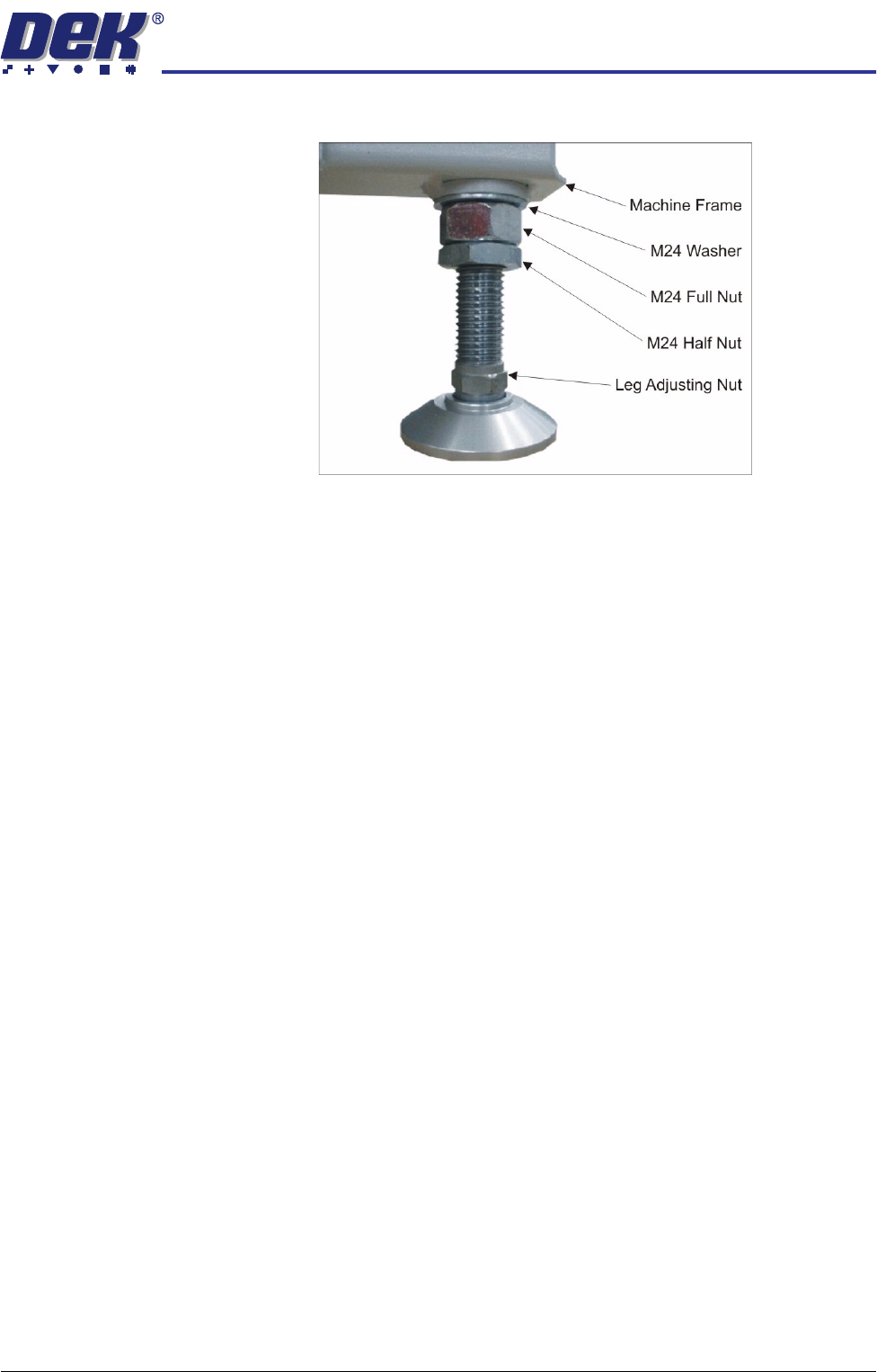
8. Replace the studs with four mounting feet.
NOTE
For machines with the anti-vibration mounting feet option, four anti-vibration
feet and one standard foot is supplied. Ensure the anti-vibration feet are
fitted to the four corners of the machine.
9. Between (and slightly forward of) the two rear mounting feet, locate the hole
and fit the fifth mounting foot.
10. Adjust the height of each foot to approximately the same height, secure in
place by tightening the nuts.
11. Move the machine to its designated position.
TRANSPORTATION
MAJOR RELOCATION
34.46 Technical Reference Manual Chapter Issue 7 Oct 06
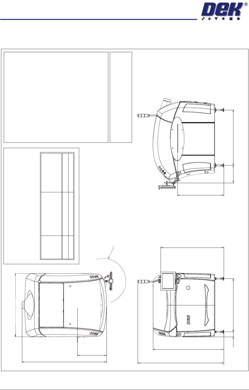
Machine Footprints
Figure 34-12 Sliding Glass Cover Footprint
R 470
Max dimension from
pivot point
Plan View
606
Front of board
1758
1334
(1352 min to 1492 max)
1472
(1665 min to 1805 max)
1785
Front View
114
1106
(1212 min to 1352 max)
1331
Side View (Right)
(840 min to
980 max)
Transfer Height 960
1150
362
Services Required
Voltage:
100V to 240V 10% Single Phase 50/60Hz±
Operating Envelope:
Temperature 10 - 35 C(50-95F)
Humidity 30 - 70% Relative Humidit
y
(non condensing)
00
Weight Boxed - 810kg, Unboxed - 660kg
Air Supply:
Air to ISO 8573.1
standard quality class 2.3.3
Pressure5-8Barat5
Litre/min
Current (with Vacuum Filtration Unit):
115V - 20 Amps
230V - 10 Amps
Current (without Vacuum Filtration Unit):
115V - 6 Amps
230V - 3 Amps
Note
All dimensions in millimetres
Board transfer height 840 - 980 mm
Screen load height 925 - 1065 mm
CAUTION
OVER CURRENT PROTECTION.
Magnetic/thermal over current protectors protect the
machines internal wiring and components from over
heating/fire during fault conditions. DEK require
additional machine suppl
y protection with the fitment of
an external circuit breaker and conforming to national/
federal regulations, .table below refers
Voltage
Value of
Circuit Breaker
(without Internal
Vac Unit)
Value of
Circuit Breaker
(with Internal
Vac Unit)
115V
230V
10 Amp
6 Amp
25 Amp
16 Amp