Printer 710_810 v8 Transportation.pdf - 第25页
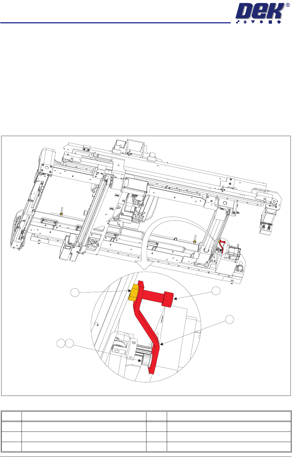
TRANS PORTATION MAJOR RELO CATION Chapter Issue 7 Oct 06 Technical Reference Manual 34.25 8. Adjust the angle of the rear chase transit bracket (12) t o align the tr ansit adjustment screw (1 1) to the centr e of the cha…
TRANSPORTATION
MAJOR RELOCATION
34.24 Technical Reference Manual Chapter Issue 7 Oct 06
3. Place a left chase transit bracket (5) over the hole on the left hand side of
the chase aligned to the rear X actuator.
4. Screw two M8 chase studs (1) through the hole in the left chase transit
bracket (5) and into the hole in the chase, engaging approximately 15mm
of thread and secure with M8 nuts (3) and M8 washers (4).
5. Ensure that an M8 nut (3) is fitted to all four M8 chase studs (1) and is
approximately 50mm down from the top of the M8 chase stud (1).
6. Place an M8 washer (4) on all four M8 chase studs (1).
7. Loosely fit the rear chase transit bracket to the rear of the left hand printhead
using an M6 cap head screw (13) and M6 washer (14).
Figure 34-10 Rear Chase Transit Bracket
Item Description Item Description
11 Transit Adjustment Screw 14 M6 Washer
12 Rear Chase Transit Bracket 15 Transit Adjustment Screw Lock Nut
13 M6 Cap Head Screw
View on Right Hand Underside
11
12
14
15
13
TRANSPORTATION
MAJOR RELOCATION
Chapter Issue 7 Oct 06 Technical Reference Manual 34.25
8. Adjust the angle of the rear chase transit bracket (12) to align the transit
adjustment screw (11) to the centre of the chase/ASM. Tighten the M6 cap
head screw (13).
9. Adjust the transit adjust screw (7), on both the left chase transit brackets (5),
and the transit adjustment screw (11) on the rear chase transit bracket (12),
so that the chase is moved approximately 5mm away from all three actuator
shafts.
10. Lock the transit adjustment screws in position with the transit adjustment
screw lock nuts (6) and (15).
11. Place the front and rear transit brackets (2) over the M8 chase studs (1).
12. Loosely attach the adaptor bracket (8) at each end of the front and rear
transit bracket (2) to the left and right printheads using an M5 cap head
screw (9) and an M5 washer (10).
13. Screw an M8 nut (3) and M8 washer (4) onto each of the four M8 chase
studs (1) and adjust so that the front and rear transit brackets are nipped
between the nuts and washers, ensuring that the chase is not lifted at this
time.
14. Fully tighten the M5 cap head screws (9) left loose in Step 12.
15. Slacken the M8 nuts (3) directly below the front and rear transit brackets (2).
16. Adjust the M8 nuts (3) above the front and rear transit brackets (2) to lift the
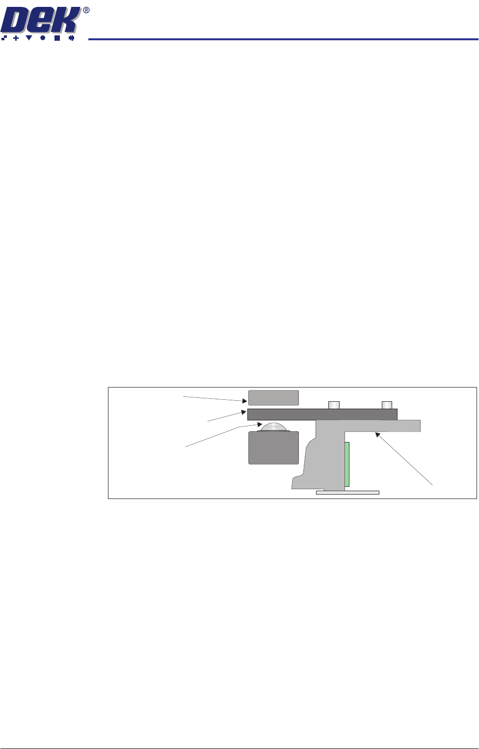
roller counter plates off the roller bearings (in all four positions), ensuring
that the roller counter plates are not touching the chase clamps.
17. Tighten the M8 nuts (3) directly below the front and rear transit brackets (2).
Chase
Chase Clamp
Roller Bearing
Roller Counter Plate
TRANSPORTATION
MAJOR RELOCATION
34.26 Technical Reference Manual Chapter Issue 7 Oct 06
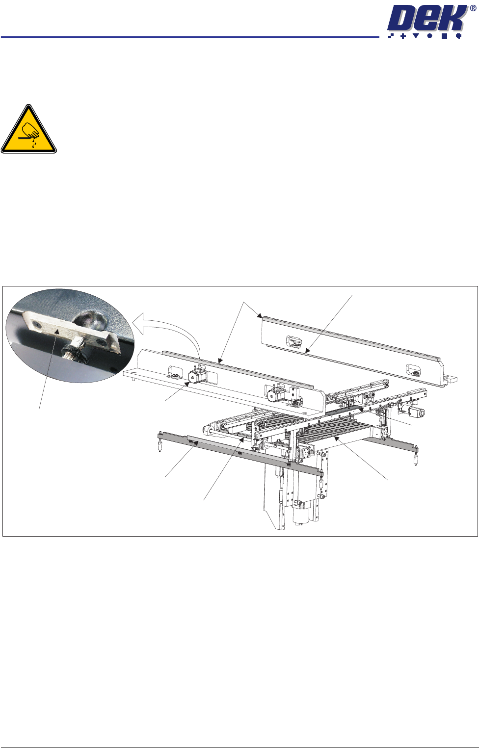
Grease Protection If the machine is being relocated to another site or placed into storage, bare
metal surfaces must be greased to protect against corrosion. Using a small
brush or cloth, apply LM grease to the following areas:
WARNING
BOARD CLAMPS. EXTREME CARE MUST BE EXERCISED WHEN WORKING IN
THE TOOLING AREA OF THE MACHINE TO AVOID INJURY. THE FOILS ON THE
FRONT AND REAR BOARD CLAMPS ARE VERY SHARP.
• Print carriage linear bearing guides (above the printheads)
• Camera linear bearing guides (below the printheads)
• Rear moving rail linear bearing guides (either side of the rising table)
• Top face of both clatter bars (either side of the rising table)
• Actuator striker plates (in 3 positions)
• Front and rear board clamps
Figure 34-11 Grease Protection
Coat the manual tooling plate with WD40 or similar product to protect the
manual tooling plate from corrosion.
Print Carriage Linear Bearing Guides
Moving Rail Linear Bearing Guide (in 2 positions)
Clatter Bar (in 2 positions)
Board Clamp
(in 2 positions)
Camera Linear Bearing Guide
(in 2 positions)
Manual Tooling Plate
Actuator (in 3 positions)
Actuator Striker Plate
(in 3 positions)