Printer 710_810 v8 Transportation.pdf - 第52页
TRANSPORT ATION MAJOR RE LOCATION 34.52 Technical Reference Manual Chapter Issue 7 Oct 06 Centre of Gravity and Seismi c Anchorage Figure 34-18 Sliding Glass Cover Mac hine (Only) Side View (right) CG L2 a b h L1 Front V…
TRANSPORTATION
MAJOR RELOCATION
Chapter Issue 7 Oct 06 Technical Reference Manual 34.51
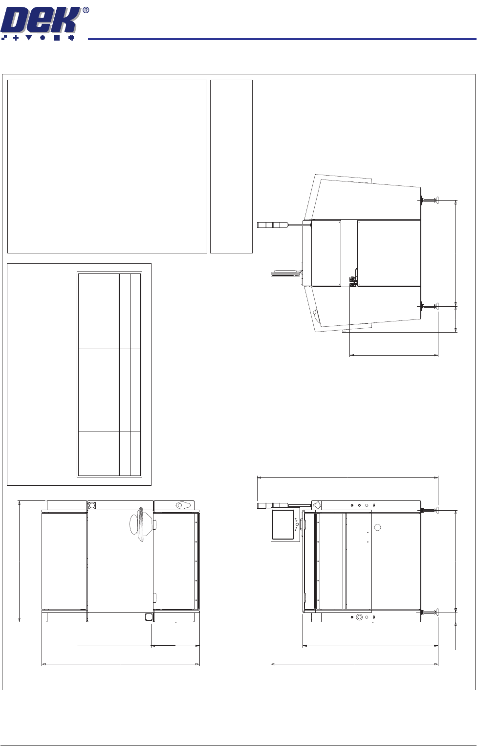
Figure 34-17 Metal Cover Footprint
Plan View
Front of board
525.5
1712.1
1314.0
Front View
1817.3
1470.0
1967.0
104.0
1106.0
Side View (Right)
(840mm Min to
980 Max)
Transfer Height 960.0
282.0
1150.0
Services Required
Voltage:
100V to 240V 10% Single Phase 50/60Hz±
Operating Envelope:
Temperature 10 - 35 C(50-95F)
Humidity 30 - 70% Relative Humidit
y
(non condensing)
00
Weight Boxed - 810kg, Unboxed - 660kg
Air Supply:
Air to ISO 8573.1
standard quality class 2.3.3
Pressure5-8Barat5
Litre/min
Current (with Vacuum Filtration Unit):
115V - 20 Amps
230V - 10 Amps
Current (without Vacuum Filtration Unit):
115V - 6 Amps
230V - 3 Amps
Note
All dimensions in millimetres
Board transfer height 840 - 980 mm
Screen load height 925 - 1065 mm
CAUTION
OVER CURRENT PROTECTION.
Magnetic/thermal over current protectors protect the
machines internal wiring and components from over
heating/fire during fault conditions. DEK require
additional machine suppl
y protection with the fitment of
an external circuit breaker and conforming to national/
federal regulations, .table below refers
Voltage
Value of
Circuit Breaker
(without Internal
Vac Unit)
Value of
Circuit Breaker
(with Internal
Vac Unit)
115V
230V
10 Amp
6 Amp
25 Amp
16 Amp
TRANSPORTATION
MAJOR RELOCATION
34.52 Technical Reference Manual Chapter Issue 7 Oct 06
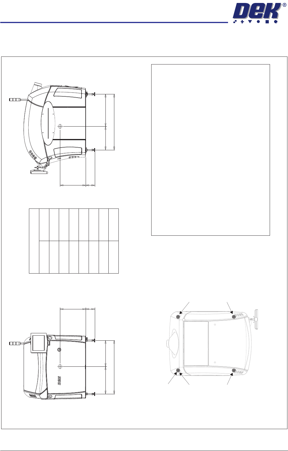
Centre of Gravity and Seismic Anchorage
Figure 34-18 Sliding Glass Cover Machine (Only)
Side View (right)
CG
L2
a
b
h
L1
Front View
CG
L3
d
b
h
c
Centre of Gravity
a
b
c
d
h
L1
L2
L3
1150mm
130mm
1106mm
530mm
485mm
565mm
665mm
541mm
Plan View
Centre of Gravity
Seismic Anchorage
Machine Feet
(in 4 positions)
Min = -100kg
Max = +400kg
Min = -100kg
Max = +400kg
Min = -100kg
Max = +400kg
Min = -100kg
Max = +400kg
Seismic Anchorage
b
The calculations for the downward and upward force of the feet
is calculated in line with the 1997 Uniform Building Code and
SEMI S2-0703. Results indicate that under worse circumstances
(calculation for hazardous fluids) an upward lifting force has to be
expected and it is strongl
y recommended to secure the machine
directly to the floor.
Appropriate attachment points may be fitted to the front and rear
of the machine base frame. For more information, contact DEK
Printing Machines.
Alternatively, the supplied machine feet can be replaced with feet
incorporating holes allowing the feet to be secured directl
y to the floor
.
Additional seismic calculations must be undertaken for the floor and
any anchor points that are used.
The length of the machine feet (measurement in the figures above)
must not exceed 130mm to meet seismic anchorage calculations.
NOTE
In the figure on the left, negative numbers are upward loads and
positive numbers are downward loads.
TRANSPORTATION
MAJOR RELOCATION
Chapter Issue 7 Oct 06 Technical Reference Manual 34.53
Grease Protection Before the machine was packaged, some areas within the machine were coated
with LM grease or WD40 to protect the metal surfaces from corroding during
transportation.
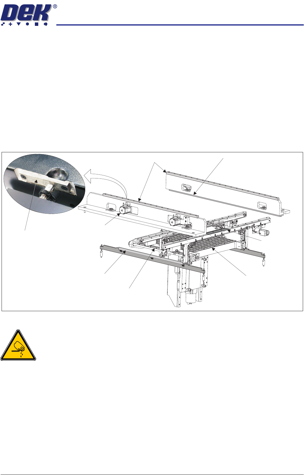
Using a lint free cloth, remove any surplus grease from the following areas,
ensuring that a light coating remains:
• Print carriage linear bearing guides (above the printheads)
• Camera linear bearing guides (below the printheads)
• Rear moving rail linear bearing guides (either side of the rising table)
• Top face of both clatter bars (either side of the rising table)
• Actuator striker plates (in 3 positions)
Figure 34-19 Grease Protection
WARNING
BOARD CLAMPS. EXTREME CARE MUST BE EXERCISED WHEN WORKING IN
THE TOOLING AREA OF THE MACHINE TO AVOID INJURY. THE FOILS ON THE
FRONT AND REAR BOARD CLAMPS ARE VERY SHARP.
The front and rear board clamp foils are greased for protection during transpor-
tation. This grease protection must to be removed completely using a lint free
cloth.
The manual tooling plate on the rising table was coated with WD40 for trans-
portation. Using a lint free cloth, wipe the manual tooling plate to remove any
residue.
Print Carriage Linear Bearing Guides
Moving Rail Linear Bearing Guide (in 2 positions)
Clatter Bar (in 2 positions)
Board Clamp
(in 2 positions)
Camera Linear Bearing Guide
(in 2 positions)
Manual Tooling Plate
Actuator (in 3 positions)
Actuator Striker Plate
(in 3 positions)