Printer 710_810 v8 Transportation.pdf - 第44页
TRANSPORT ATION MAJOR RE LOCATION 34.44 Technical Reference Manual Chapter Issue 7 Oct 06 3. Replace t he four corn er mounti ng feet wit h four t ransport ation st uds, ensur- ing that the shor test length of exposed th…
TRANSPORTATION
MAJOR RELOCATION
Chapter Issue 7 Oct 06 Technical Reference Manual 34.43
Transportation If the machine is to be relocated to another site it is recommended that it is
encased in its original transportation box, or if not available, a new transporta-
tion box may be obtained from DEK Printing Machines Ltd.
If the machine is to be transported by sea freight, packing advice should be
sought from specialist freight companies.
WARNING
MACHINE LIFTING. TO PREVENT SERIOUS INJURY TO PERSONNEL, DURING
LIFTING AND TRANSPORTATION OPERATIONS, ENSURE THE MACHINE IS
LIFTED AND TRANSPORTED IN ACCORDANCE WITH INSTRUCTIONS
DETAILED IN THIS SECTION.
CAUTION
MACHINE DAMAGE.
Damage to the machine will occur if the machine is
lifted:
• Using lifting strops
• From the sides
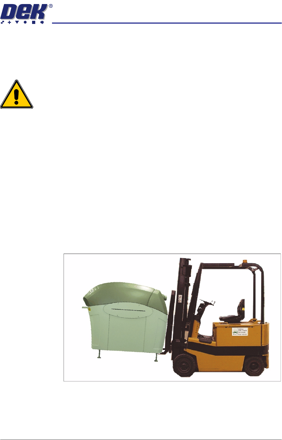
The machine may be lifted using a fork-lift truck or similar machine that meets
the following criteria:
• Minimum fork length of 1372mm (54 inches)
• Fork span >686mm (27 inches) and <914mm (36 inches)
• Fork Height (thickness) <50mm (2 inches)
• Lifting capability of 2000kg
1. Locate the forks under the machine base (preferably from the rear so the
weight of the machine is taken evenly on the front and rear cross members).
2. Raise the machine and remove the five mounting feet.
TRANSPORTATION
MAJOR RELOCATION
34.44 Technical Reference Manual Chapter Issue 7 Oct 06
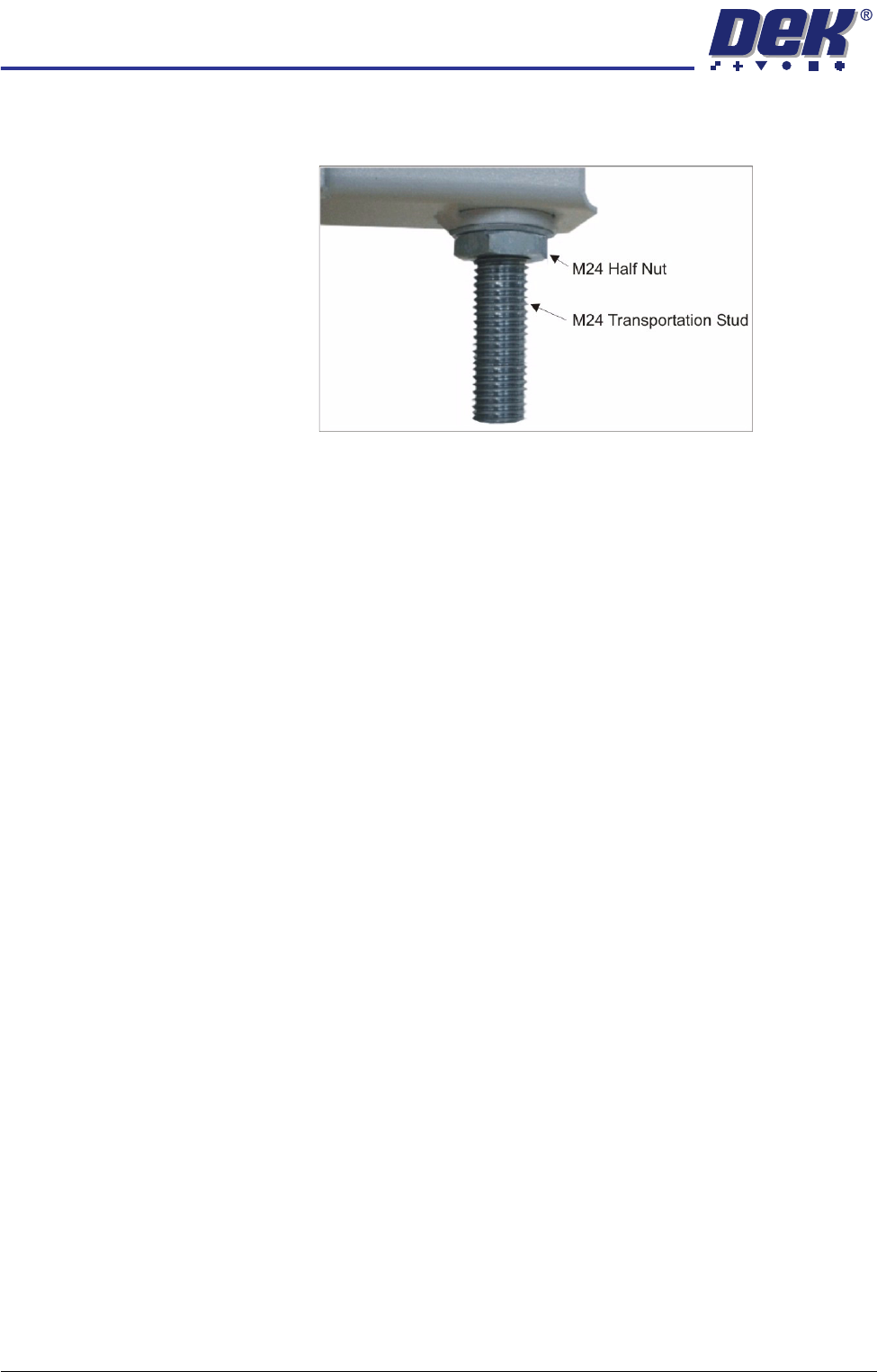
3. Replace the four corner mounting feet with four transportation studs, ensur-
ing that the shortest length of exposed thread, screws into the machine.
4. Place the machine on the base of the transportation box.
5. Relocate the forks under the base of the transportation box.
6. Raise the forks to gain access to the underside of the base of the transpor-
tation box.
7. Fit the four washers and nuts to secure the machine to the base of the
transportation box.
8. Lower and remove the forks.
9. Secure the sides and top of the transportation box with screws.
10. Wrap the loose items and pack separately. The machine is now ready for
transportation.
Unpacking 1. Unscrew the transportation box securing screws and remove the lid and
sides of the delivery crate.
2. Using the fork lift truck, locate the forks under the base of the transportation
box.
3. Raise the forks to gain access to the underside of the base of the transpor-
tation box.
4. Remove the four nuts and washers securing the machine to the base of the
transportation box using a 36mm spanner (wrench).
5. Lower the forks and relocate the forks under the machine base (preferably
from the rear so the weight of the machine is taken evenly on the front and
rear cross members).
6. Raise the forks, separating the machine from the base of the transportation
box.
7. Remove the four studs that secured the machine to the base of the trans-
portation box.
TRANSPORTATION
MAJOR RELOCATION
Chapter Issue 7 Oct 06 Technical Reference Manual 34.45
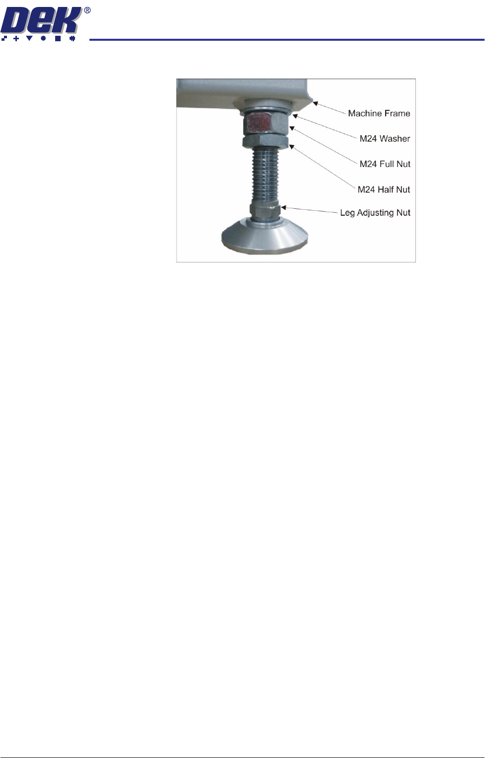
8. Replace the studs with four mounting feet.
NOTE
For machines with the anti-vibration mounting feet option, four anti-vibration
feet and one standard foot is supplied. Ensure the anti-vibration feet are
fitted to the four corners of the machine.
9. Between (and slightly forward of) the two rear mounting feet, locate the hole
and fit the fifth mounting foot.
10. Adjust the height of each foot to approximately the same height, secure in
place by tightening the nuts.
11. Move the machine to its designated position.