Printer 710_810 v8 Transportation.pdf - 第60页
TRANSPORT ATION MAJOR RE LOCATION 34.60 Technical Reference Manual Chapter Issue 7 Oct 06 7. Loosen the trans it adjustment screw lock nut (15) on the rear chase transit brack et (12). Figure 34- 24 Rear Chase T ransit B…
TRANSPORTATION
MAJOR RELOCATION
Chapter Issue 7 Oct 06 Technical Reference Manual 34.59
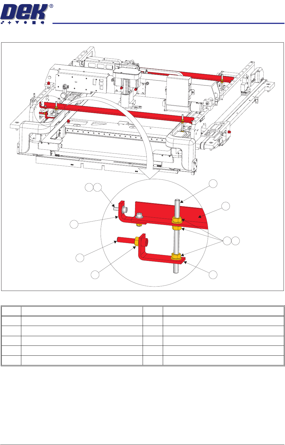
Figure 34-23 Front and Rear Transit Brackets
Item Description Item Description
1 M8 Chase Stud 6 Transit Adjustment Screw Lock Nut
2 Front/Rear Transit Bracket 7 Transit Adjustment Screw
3 M8 Nut 8 Adaptor Bracket
4 M8 Washer 9 M5 Cap Head Screw
5 Left Chase Transit Bracket 10 M5 Washer
9
1
2
3
4
5
6
7
8
10
TRANSPORTATION
MAJOR RELOCATION
34.60 Technical Reference Manual Chapter Issue 7 Oct 06
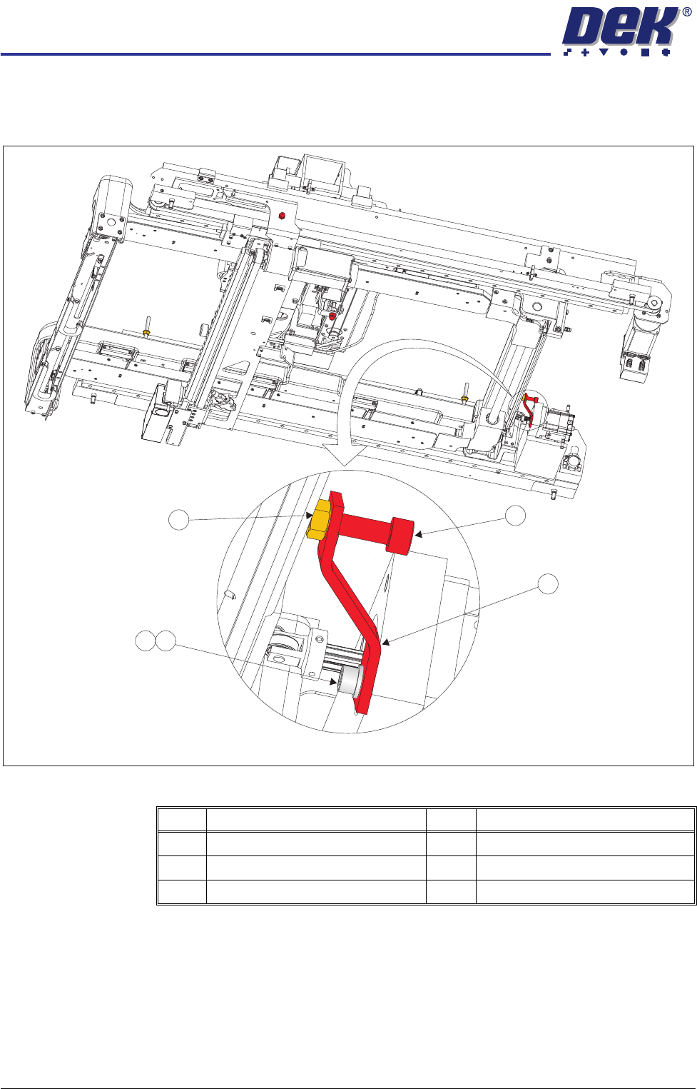
7. Loosen the transit adjustment screw lock nut (15) on the rear chase transit
bracket (12).
Figure 34-24 Rear Chase Transit Bracket
8. Using a 6mm Allen key, loosen the transit adjustment screw (7), on both the
left chase transit brackets (5), and the transit adjustment screw (11) on the
rear chase transit bracket (12), so that the chase comes into contact with
the three actuator shafts.
9. Using a 5mm Allen key, remove the rear chase transit bracket (12) by
removing the M6 cap head screw (13) and M6 washer (14).
Item Description Item Description
11 Transit Adjustment Screw 14 M6 Washer
12 Rear Chase Transit Bracket 15 Transit Adjustment Screw Lock Nut
13 M6 Cap Head Screw
View on Right Hand Underside
11
12
14
15
13
TRANSPORTATION
MAJOR RELOCATION
Chapter Issue 7 Oct 06 Technical Reference Manual 34.61
10. Loosen the M8 nut (3) that secures the left chase transit bracket (5) to the
chase on the front and rear transit brackets.
11. Unscrew the M8 chase studs (1) from the chase and remove from the
machine.
12. Remove the two left chase transit brackets (5) from the machine.
13. Remove the two right hand chase studs (1) by loosening the two M8 nuts
(3) that secure the chase studs (1) to the chase.
CAUTION
TRANSIT SCREWS.
The transit screws are constructed of a red plastic
dome head nut and a 45mm steel grub screw. Although the two parts are
bonded, ensure that both parts are removed if they become separated.
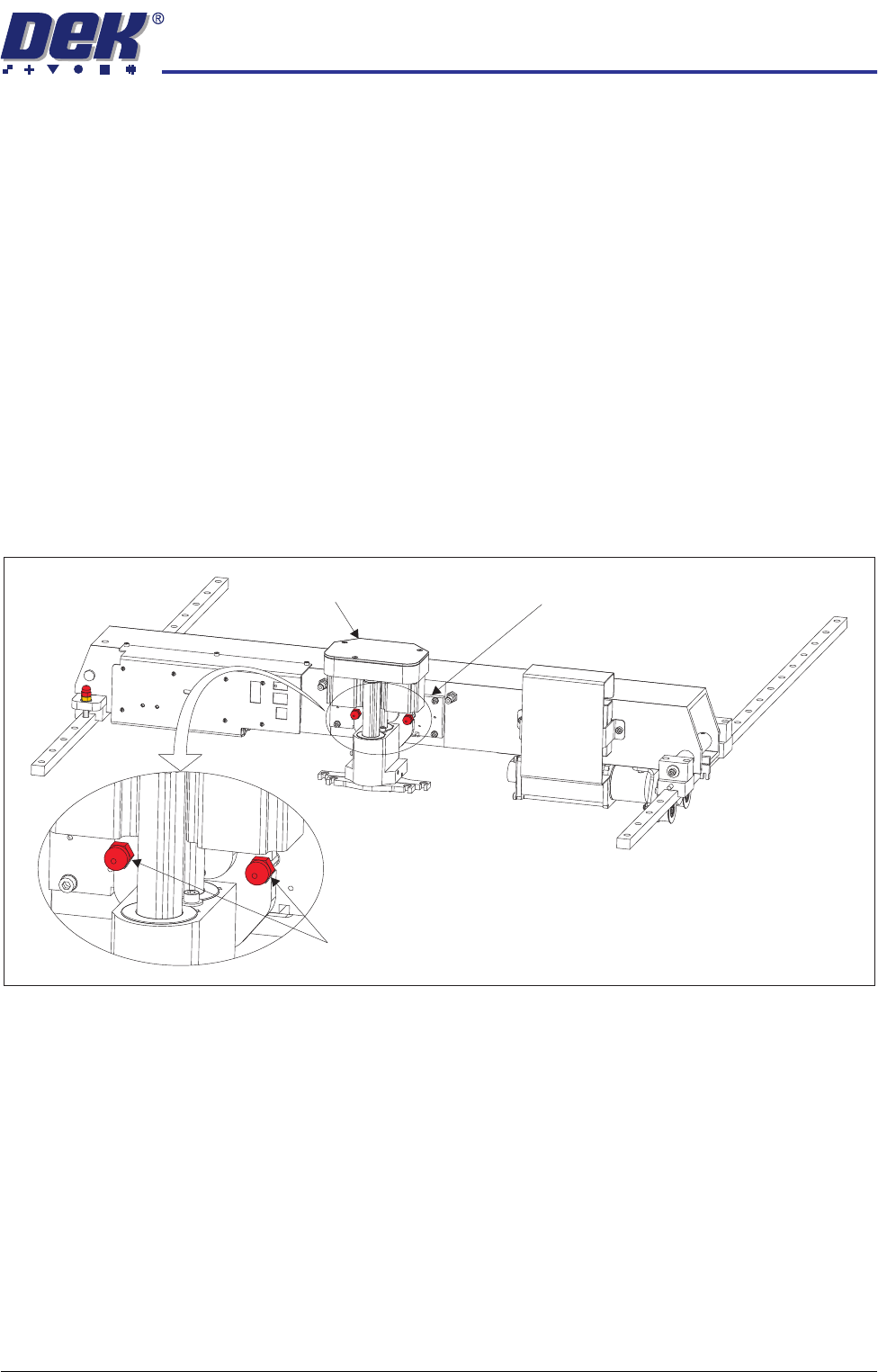
Squeegee Transit
Screws
1. Snip the cable ties securing the piece of card to the front of the squeegee
mechanism. Remove the cable ties and the piece of card from the machine.
2. Whilst supporting the squeegee mechanism, remove the two squeegee
transit screws.
Squeegee Transit Screws
Squeegee Mechanism Squeegee Mount